


If the PIN code query is enabled, check that the ARC600 configurator
has the correct PIN code entered in the wireless WAN submenu.
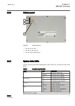
3.2
I/O connections
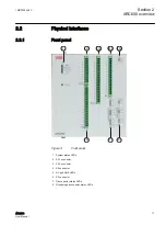
The device has four connectors in the front panel for power input and for switching
devices' status monitoring and control, battery condition monitoring, battery charging
and measurement functions.
3.2.1
Power connector
Operating power for the device is supplied from connector X2.1. The device can use
either an unregulated AC line input or a regulated DC input.
The power switch is located on the serial panel. It turns the unit on and off.
Table 9:
Operating voltages of X2.1 connector pins
Input pins
Operating voltage range
1 and 2 (AC)
90...264 V AC or 85...200 V DC
6 and 7 (DC)
20...30 V DC
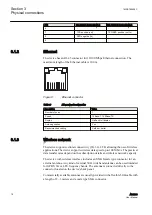
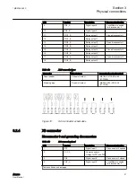
3.2.2
X2.1 connector
Table 10:
X2.1 connector pinout
Pin
Symbol
Description
1
L
230 V AC
2
N
230 V AC
3
NTC_A
NTC resistor (battery
temperature comp.)
4
PE
Protective earth
5
NTC_B
NTC resistor (battery
temperature comp.)
6
24VDC
24 V DC output/input
7
GND
DC ground
8
GND
DC ground
9
GND
DC ground
10
BAT
Battery charging
1MRS758459 C
Section 3
Physical connections
ARC600
19
User Manual