MANUAL No. 3AAM101052 E
Installation, Operation, and MaintenanceInstructions
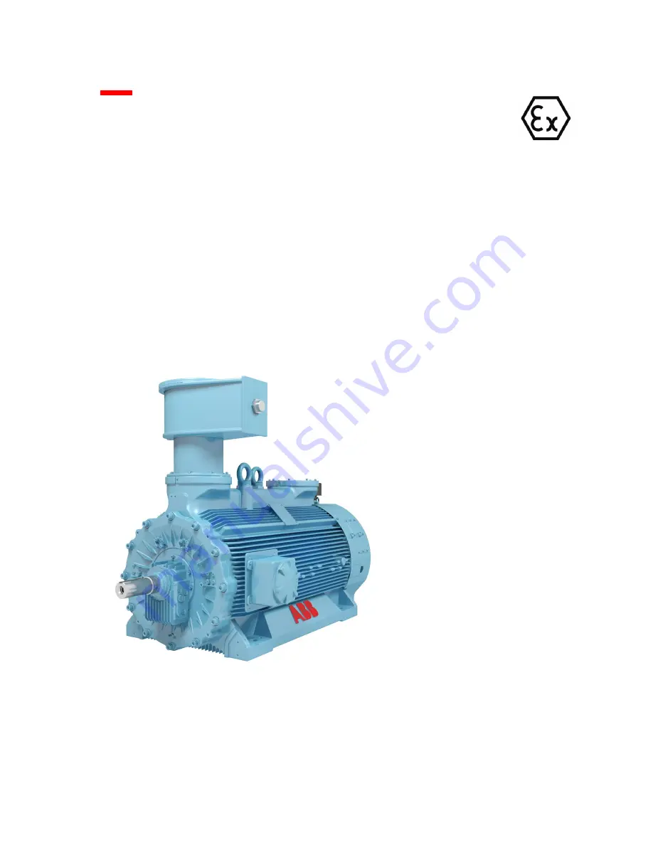
High voltage flameproof motors for explosive gasatmospheres
AMD Rg 355-400-450-500
Revision C
Issue date: January 2023
(ORIGINAL INSTRUCTIONS)
Page 1: ...No 3AAM101052 E Installation Operation and Maintenance Instructions High voltage flameproof motors for explosive gas atmospheres AMD Rg 355 400 450 500 Revision C Issue date January 2023 ORIGINAL INSTRUCTIONS ...
Page 2: ...ions 3AAM101033 E Rev B Operations prior to commissioning Mechanical operations 3AAM101034 E Rev B First commissioning and supervision of operation 3AAM101035 E Rev B Operation faults 3AAM101036 E Rev B Section 3 Maintenance General maintenance and revision criteria 3AAM101037 E Rev B Maintenance plan 3AAM101038 E Rev B Rolling bearings check Impact impulses measurement 3AAM101039 E Rev B Rolling ...
Page 3: ...Installation Operation and Maintenance Instructions High voltage flameproof motors for explosive atmospheres AMD Rg 355 400 450 500 SECTION 1 General information and safety rules ...
Page 4: ...ed by this Manual done by non qualified personnel is strictly forbidden REMARK For qualified personnel see for example the Standard IEC 60364 must be intended workers that owing to their technical instruction degree to their specific experience to the received instructions and to their knowledge of General technical rules Specific technical rules regarding the job and the installations on sites wh...
Page 5: ...the following protection modes Ex db Explosion proof motor coupled with an Ex db main terminal box type suitable to operate in a potentially explosive atmosphere with presence of gases group IIB or IIC with a temperature class of T3 T4 or T5 Alternatively they can operate in mines full of firedamp typical of Group I applications Ex db eb Explosion proof motor coupled with an Ex eb main terminal bo...
Page 6: ...The fan is located into a ventilation hub driving axially the air flux on the cooling ribs of the motor frame This cooling method is the standard solution for motors operating at practically constant speed direct feeding from the mains Normally the fan has varnished steel blades In some cases can be provided with reinforced polyammidic plastic blades Non standard motors are provided with aluminum ...
Page 7: ...ones under voltage have high torque rotating parts and occasionally hot surfaces 1 4 1 2 OPERATION The motors covered by this Manual are intended for use in industrial installations The general operating and functional characteristics are in accordance with the requirements of the harmonized series of motors described by the IEC EN 60034 VDE 0530 Standard In particular the electromechanical design...
Page 8: ...ed techniques for drying 1 4 1 4 INSTALLATION The installation on site of the motors shall be done in accordance with the requirements of the IEC EN 60079 14 Standard REMARK The personnel in charge with the final checks and the formal authorization for putting the machines into service and with the operation on the plants in areas where a gas explosion danger can exist must be skilled and qualifie...
Page 9: ...suitable mechanical protection degree IP reported on the nameplate If it would be necessary to use different type of cable glands devices it is compulsory that the used cable glands are of certified type Ex db o Ex eb depending on the type of protection reported in the nameplate and that the cable glands are fixed to the terminal boxes respecting the requirements of the European Standard The respo...
Page 10: ...s of the shaft operation with vibration level within the tolerable field according to the ISO 10816 Standard is absolutely not suggested The ventilation channels and the frame fins shall be always clean inspection at regular time interval shall be scheduled If the motor is provided with drain plugs they shall be opened inspected for cleanness and tightness and reclosed The regreasing of the antifr...
Page 11: ...r modifications of the various motor components Component Protection Remarks db db eb Frame no no Endshields no no Bearing seals no no Main and auxiliary terminal boxes no yes 1 1 Maintain the original mechanical integrity and IP protection Insulators no no Thread on cables glands no yes 2 2 Maintain the original IP protection Stator core no 3 no 3 3 Only minor repairs allowed Stator rewinding yes...
Page 12: ... Avoidance of a build up of electrostatic charge on Group I or Group II electrical equipment and Table 9 Limitation of thickness of non metallic layer in IEC EN 60079 0 Standards the paint system related to the motor and or the enclosures is made with no conductive paint type and presents a maximum thickness 200 μm for gas group IIC and a maximum thickness 2000 μm for gas group IIB Alternatively i...
Page 13: ... terminal boxes with insulated phases type E1LISE and E1LISR are used the power supply connection shall be made with kit of connectors Euromold or insulated junction Raychem supplied by ABB and fixed on cable by the user according to the manufacturer s instruction If these terminal boxes are equipped with special coils assembly for a detector system of partial discharges they shall be use accordin...
Page 14: ...ng as per IEC EN 60079 0 and IEC EN 60079 1 Standards is present The marking contains Ex symbol which indicates that the motor has been designed and manufactured to operate in potentially explosive atmosphere Level of Protection db db eb tb tc Group identifying the nature of the potentially explosive gas or dust or firedamp if available for which the flameproof motor was intended and designed IIB ...
Page 15: ...tion and main terminal box in Ex eb execution 0537 II 2D Ex tb IIIC T125 C T150 C Db 0537 I M2 Ex db I Mb NOTE T5 only for AMD Rg 355 400 450 When Ex i RTDs that are certified as Ex component are required in the stator winding the motor marking includes the level of protection ib in the marking above Motors are designed to respect the following requirements stated in IEC 60079 0 Explosive Atmosphe...
Page 16: ...Small M Medium L Large 4 Number of poles 2 4 5 Cooling Type R Rib cooled 6 Mounting arrangement B Horizontal V Vertical 7 Bearing type A Antifriction bearing S Sleeve bearings IIB only 8 Protection type B Explosion proof enclosure for Equipment Group IIB C Explosion proof enclosure for Equipment Group IIC M Explosion proof enclosure for Mines susceptible to firedamp Group I 9 Alternative variants ...
Page 17: ... 355 400 450 500 Internal view of motor components with horizontal and vertical axis Issued by MOLM We reserve all rights in this document and in the information contained therein Reproduction use of disclosure to third parties without express authority is strictly forbidden Variant for sleeve bearings Horizontal axis rolling bearings AMD Rg 355 400 DE NDE SIDES ...
Page 18: ...tmosphere AMD Rg 355 400 450 500 Internal view of motor components with horizontal and vertical axis Issued by MOLM We reserve all rights in this document and in the information contained therein Reproduction use of disclosure to third parties without express authority is strictly forbidden Vertical variant rolling bearings AMD Rg 355 400 IM3011 ...
Page 19: ...ve atmosphere AMD Rg 355 400 450 500 Internal view of motor components with horizontal and vertical axis Issued by MOLM We reserve all rights in this document and in the information contained therein Reproduction use of disclosure to third parties without express authority is strictly forbidden Horizontal axis rolling bearings AMD Rg 450 500 ...
Page 20: ...atmosphere AMD Rg 355 400 450 500 Internal view of motor components with horizontal and vertical axis Issued by MOLM We reserve all rights in this document and in the information contained therein Reproduction use of disclosure to third parties without express authority is strictly forbidden Horizontal axis Variant sleeve bearings AMD Rg 450 500 ...
Page 21: ...atmosphere AMD Rg 355 400 450 500 Internal view of motor components with horizontal and vertical axis Issued by MOLM We reserve all rights in this document and in the information contained therein Reproduction use of disclosure to third parties without express authority is strictly forbidden Vertical variant rolling bearings AMDR 450 500 IM4011 ...
Page 22: ...iary terminals box if foreseen in order 09 Internal flame arrester closure DE side 25 Sleeve bearing DE and NDE sides only for horizontal axis 10 Internal flame arrester closure NDE side 26 Internal oil seal DE and NDE sides only for horizontal axis 09a Labyrinth flame arrester internal closure for sleeve bearings DE side 27 External oil seal DE and NDE sides only for horizontal axis 10a Labyrinth...
Page 23: ...perature is about 10 C higher than that of the outside air The size of the rooms should permit a safe and accessible storage arrangement Take care to protect the machines against possible insects such as termites and rodents Check regularly the moisture content in the cases if any Pay attention to the carrying capacity of the floor Do not stack heavy goods on top of each other Always lay base fram...
Page 24: ...g Patch the wrapping with tape or if possible weld it Exceptions to the previous instructions Wrappings for storage of limited duration have a sufficient quantity of desiccant to last for the period in question These cases do not have any openings or chemical indicators With shipments packed in cases without openings remove the lid of the case carefully and examine the wrapping for punctures Speci...
Page 25: ...e cleaned and dried by blowing through with warm air before packing It must be ensured that they are still clean and dry before the machines are conserved Space heaters Space heaters must remain switched on in order to avoid condensation within the machine Periodically check that they are operating Openings If there are any openings where cables are not connected up to terminal boxes or piping to ...
Page 26: ...the machine Signature of the consignee DATE SIGNATURE Transport damage to motor and or accessories Yes No In case of damage use control list 2 Missing parts at delivery Yes No In case of missing parts use control list 3 Motor storage period longer than 6 months Yes No In case of long storage use control list 4 Mechanical installation control list 5 Electrical installation control list 6 Test run 1...
Page 27: ...sclosure to third parties without express authority is strictly forbidden Customer Machine type Machine serial n Arrival date of the machine Signature of the consignee Damages Actions taken Machine Accessories Photographed Registered Package Reported to Reported to supplier insurance Company Other Dispatched by To carrier Railway Lorry truck Airfreight Post Mail Shipped by the m s Other Damages fo...
Page 28: ...bidden Customer Machine type Machine serial n Arrival date of the machine Signature of the consignee Missing parts or comments Check the list of parts while unpacking the motor All damages including those to the transportation package should be photographed Damages or mis sing parts should be reported immediately to the forwarding agent the insurance Company and to ABB After unpacking store parts ...
Page 29: ...checked material is used Rotor is turned 10 revolutions Storage place is vibration free Air is free of every two months corrosive gases only antifriction bearings In case of machine idle for more than 6 months Repeat the conservation procedures Insert another drying pack into the bearing In case of machine idle for more than 1 year Dismantle the sleeve bearings Store and protect the sleeve bearing...
Page 30: ...thority is strictly forbidden Customer Machine type Machine serial n Measures Foundation according to drawing Alignment checked according to instructions Foundation bolts tightened with torque wrench Assembly of coupling half checked Bearings filled with lubricant type Bearings filled with lubricant quantity Assembly of oil and coolant pipes checked Flanges tightened Stator terminal box mounted co...
Page 31: ...coupling displaced to left of the right hand one moved to left by 0 1 mm Check for measuring error a b c d 1 a b c d 1 1 1 1 2 2 2 2 25 31 1 28 28 28 28 38 18 Schematic for table 1 Axial gap and misalignment The axial gap is determined by taking readings from the two dial indicators AI and AII whereby the first reading from the top indicator AI is designated by e1 and that from the bottom indicato...
Page 32: ...a Machine Machine Voltage V VAC Voltage V VAC Frequency Hz Frequency Hz Space heater V VAC Space heater V VAC External blower motor V VAC External blower motor V VAC Insulation test Winding Rinsul measured at V Vcc Winding temperature C Rinsul value after 1 min M R insul 40 C 104 F M Rinsul value after 10 min M R insul 40 C 104 F M See the section Winding maintenance of electrical machine Main pro...
Page 33: ...his document and in the information contained therein Reproduction use of disclosure to third parties without express authority is strictly forbidden Monitoring equipment Temperature monitoring Alarm C F Trip C F In stator winding In bearing In Flow or pressure monitoring m3 s o Pa Alarm Trip ft3 s o psi Lubricating oil min Lubricating oil max Other Vibration Comments For record files To From Date...
Page 34: ...den Customer Machine type Machine serial n Date Name of supervisor Connections Supply cables connected Auxiliary devices connected First start Direction of rotation clockwise counter clockwise as seen from drive end Noise normal abnormal Second start to full speed Run normal abnormal Noise normal abnormal Vibration normal abnormal Run OK operation stop why Time Bearing temp Oil Comments Stator D e...
Page 35: ...production use of disclosure to third parties without express authority is strictly forbidden Machine serial n Coupling connected On load Acceleration time Coupling disconnected At no load Time Bearing temp Winding temperature Stator Vibration Load or D end N end U T1 V T2 W T3 Current Power mm sec m inch sec mils W date C F C F C F C F C F A factor D end N end HP Comments For record files To From...
Page 36: ...r of starts during week Operating hour during week Comments Loggings of operational data and remarks should be kept for reference during maintenance work trouble shooting and repairs Year Week Mon Tues Wed Thurs Fri Sat Sun Point of inspection Date Load W HP Absorbed current A Fault indication Yes No Bearing temp D end C Bearing temp N end C Oil level Normal Abnormal Oil leakages Yes No Winding te...
Page 37: ...ting hours Number of starts Bearings Lubricant change Lubricant type Quantity Oil filter change Oil filter type Flanges and pipes checked Comments Cooling Cooling ribs cleaned Cooling tubes cleaned Air filter checked Cleaned External fan checked Comments Electric components Connection of high voltage cables checked Connection of control cables checked Space heater checked Machine opened and inspec...
Page 38: ...rent Amp Random inspection Load kWatt Running hours 1 Bearings seals OKObservations Grease injectors and grease outlet OKObservations 2 Contaminations Stator Rotor Air passages Ends Remarks winding cage tubes or ribs D N Total amount of dirt Grease oil Dry dirt dust Dampness rust 3 Inspection results OK Observations D N 3 1 Windings Supports Coils Connection cables 3 2 Stator core Core laminations...
Page 39: ...Installation Operation and Maintenance Instructions High voltage flameproof motors for explosive atmospheres AMD Rg 355 400 450 500 SECTION 2 Installation commissioning and operation ...
Page 40: ...centre tolerance that is 0 1 mm respect the dimension indicated on the outline drawing and makes easy the future installation of possible replacement machine Warning The explosion proof motors have a very reduced backlash between the bearings anti fire seals and the rotor shaft For this reason it is necessary to pay attention during the installation of the machine on its foundations and in particu...
Page 41: ...ry Dry foundation holes for bolts 6 and pack out with elastic filler 13 to 5 10 mm below top edge recommend a granular synthetic filling compound e g LUSTREX Polystyrene 2220 or 4220 Supplier MONSANTO PLASTICS RESINS CO 800 N Lindbergh Blvd St Louis No 63166 USA Sand may not be used as a filler After packing out with filler 13 seal top of foundation holes with an oil resistive elastic sealing comp...
Page 42: ...n the motor Align the motor with the leveling screws and the shims than tighten the bolts 7 Test before coupling A test run is suggested before the coupling halves of the joint to the mating machine is connected Refer to the commissioning instruction Levelling spindle Sole plates Bedplate with foundation anchor bolts Sole plates Bedplate with foundation through bolt Fig 1 Fig 2 retighten Fig 3 1 S...
Page 43: ...es for foundation and mountings are similar to the rules for horizontal mounting arrangement See Sheet No 3AAM101029 In general vertical machine are mounted on a separately prepared steel foundation plate Installation on a steel foundation plate Check fastening holes in steel foundation plate clean seating surfaces set down machine and align Couple machine and bolt up in operating location Tighten...
Page 44: ...oil on the shaft extension and hub bore is to be recommended In general the coupling manufacturer s instructions are valid for mounting and removing the coupling hubs It is common practice to heat the coupling in order to increase or make the clearance between the two fitting parts If the coupling is keyed there is a certain clearance between the coupling and the shaft extension so heating the cou...
Page 45: ...plate and rods to exert an axial force between the shaft end and the inner surface of the coupling In other words the force generated with the jack must push the coupling out of the shaft end Sustain with a suitable crane the weight of the coupling to avoid that the coupling will load the shaft end and the fall of the coupling itself Connect the high pressure device at the threaded hole provided f...
Page 46: ...ng radial displacement on the cold machine then the rule is that zero displacement should be set ALIGNMENT The following must be observed when coupling two or more machines together The coupling halves must be exactly aligned to each other following the fundamental rule that the shaft train is to be exactly horizontal or vertical for vertical machines The shaft being coupled must naturally be exac...
Page 47: ...salignment a1 b1 c1 and d1 are readings from the dial indicator R at the locations a top b bottom c right d left The readings are entered in the formulas to obtain the values of radial misalignment Table 1 Fig 1 Table 1 Measuring location 1st Measurement 2nd Measuremt Example measures in hundredth of mm Vertical Top a1 a2 25 28 Bottom b1 b2 31 28 Difference a1 b1 a2 b2 6 0 Half difference misalign...
Page 48: ...op Lateral Gap Left i1 l1 40 36 Right k1 m1 48 40 Gap k i l m 1 1 1 1 2 6 2 40 36 40 48 The gap is greater at the left The gap is greater by Fig 2 The gap is greater at the right 0 06 mm at the left Schematic for Table 2 Radial misalignment of the two coupling halves must be read in the 4 position each of 90 at same distance In the example it is assumed that an axial movement of the shaft of 0 2 m...
Page 49: ...ger or similar apply a steady direct voltage between the winding being tested and the machine parts connected to ground the resistance measurement is to be carried out one minute after the voltage is applied Any parts of the winding not being tested and the temperature detectors are to be connected to ground Usually a three phase winding is measured as a whole but if the centre star connection can...
Page 50: ... C 140 C Release 150 C 145 C The above limits ensure that the maximum surface temperature of the machines cannot exceed the limits of the assigned temperature class T3 or T4 For machines supplied by inverter the limits indicated are to be reduced by approx 15 C to take into account this heavy duty operating condition ELECTRICAL CONNECTIONS Warning During the installation operations no drilling is ...
Page 51: ...23 Page 3 of 3 We reserve all rights in this document and in the information contained therein Reproduction use of disclosure to third parties without express authority is strictly forbidden Warning when working on circuits that may be live take all the necessary precautions Ex eb Main terminal box Ex db IIB IIC Ex eb IIC Auxiliary Terminals Box aluminum material Ex db IIB IIC Ex eb IIB IIC Auxili...
Page 52: ...E side with a vent tube with filter coming out from the ventilation hub to avoid the pressurisation of the bearing enclosure Separately cooled plain bearings The bearings are connected to an oil supply system which should be in operation before the machine is started up and remain in operation until the machine is turned down The maximum oil inlet temperature of the bearings should not exceed 65 C...
Page 53: ...ed from the entrained air The oil tank must be fitted with a condensation separator and if required by low ambient temperature also with a heater A suitable internal protection against corrosion will help to avoid oil contamination The oil return line must enter the oil tank above the oil level Var A Should the oil return line be immersed vent holes must be provided so that oil borne air can escap...
Page 54: ...itched off Test start Before the first start up of the motor check the correct insertion of the dowel pins if any between the frame feet and the basement After all devices except the coupling to the driven machine have been connected proceed to the first starting The first start should last only about one second Check that the direction of rotation is right and that there is no obstacle deterring ...
Page 55: ...ess of grease After few hours the excess grease will be discharged and the bearings temperature will return at normal values Horizontal motors with sleeve bearings After the start up check that there is no contact between stationary and rotating parts and that no abnormal noise is coming from the motor Pay attention to the oil tightness of the tubes connections It is recommended a bearing full ins...
Page 56: ...formation contained therein Reproduction use of disclosure to third parties without express authority is strictly forbidden Early identification of abnormal operation symptoms and rapid remedial action are essential as a means of preventing minor fault from developing into really serious trouble later on The following trouble shooting flow charts may help you to trace and remedy possible faults Al...
Page 57: ...lease contact the supplying ABB Company 2 Starting system can be star delta connection starting reactor or auto transformer When a starting system different than the direct on line starting the machine torque decrease and the starting time increase This must be noticed 3 Driven machines may have different starting methods Many of them can be started without load For example compressors and blowers...
Page 58: ... 3AAM101036 E Rev B Page 3 of 8 01 2023 We reserve all rights in this document and in the information contained therein Reproduction use of disclosure to third parties without express authority is strictly forbidden B Faults during running at no load C Faults during running under load Overheating 1 For example machines can be partioned off or if the room temperature is too high an air conditioning...
Page 59: ...on motors Issued by MOLM Sheet No 3AAM101036 E Rev B Page 4 of 8 01 2023 We reserve all rights in this document and in the information contained therein Reproduction use of disclosure to third parties without express authority is strictly forbidden D Faults during no load or on load running Abnormal noise localised overheatings smoke etc E Faults during no load or on load running High vibration le...
Page 60: ...ng housing Replace worn seals or improve the seal design to obtain adequate protection x x x x x Foreign matter acting as corrosive Water acids paints or other corrosives are entering the bearing housing Install a protective shield and or fingers to guard against foreign matter Improve seals x x x x x Foreign matter in the bearing housing Chips dirt etc were not removed from housing before assembl...
Page 61: ... reserve all rights in this document and in the information contained therein Reproduction use of disclosure to third parties without express authority is strictly forbidden x x Bearing noisy Bearing is exposed to vibration while the motor is idle Carefully examine the bearing for wear spots corresponding to the spacing of rolling elements For standby equipments ball bearings are better suited tha...
Page 62: ...50 500 Operating faults Trouble shooting information for Squirrel Cage Induction motors Issued by MOLM Sheet No 3AAM101036 E Rev B Page 7 of 8 01 2023 We reserve all rights in this document and in the information contained therein Reproduction use of disclosure to third parties without express authority is strictly forbidden ...
Page 63: ...50 500 Operating faults Trouble shooting information for Squirrel Cage Induction motors Issued by MOLM Sheet No 3AAM101036 E Rev B Page 8 of 8 01 2023 We reserve all rights in this document and in the information contained therein Reproduction use of disclosure to third parties without express authority is strictly forbidden ...
Page 64: ...Installation Operation and Maintenance Instructions High voltage flameproof motors for explosive atmospheres AMD Rg 355 400 450 500 SECTION 3 Maintenance ...
Page 65: ...s recommendations based on many years of experience The time intervals are based on an 16 hours operating day under normal conditions The actual circumstances under which the machines operate are often quite different so that for each particular case certain time intervals may need to be adapted to the prevailing site conditions such as dirt deposits loading switching frequency etc The recommended...
Page 66: ...differentiated between emergency spare parts which should be available at the plant even before commissioning and parts which are recommended for long term stocking When one or more operators in a given area have a number of identical machines in operation then it could be advantageous to form a spare parts pool Reconditioning work general All bare components or parts thereof are to be cleaned see...
Page 67: ...ator winding Measure temperature at provided measuring points e g built in RTD s 1 Measure dielectric resistance 1 Dielectric condition diagnosis Visual inspection of machine inside and outside Visual check at all accessible points for rust 3 Main terminal box Visual check for cleanness and absence of moisture from condensation Check for tightness and state of conductors terminals and locking elem...
Page 68: ...n experience show that 1 Monitoring the bearing condition is only of value if the initial SV measurement is taken and recorded during the running tests in the manufacturer s works or at commissioning record sheets issued by the measuring instrument manufacturer e g SPM should be used and later handed over to the customer 2 The initial SV measurement could already lie in the range fair yellow Howev...
Page 69: ... standards specify the minimum physical chemical properties for the lubrication greases All lubricant suppliers classify their products and are able to suggest which is most appropriate To select the re lubrication grease bear in mind the following For re lubrication only greases with the same soap base as that already in the bearing are to be used Rolling bearings are filled in the factory with a...
Page 70: ... signs of rust using a fine oil stone If it is not possible to paint spread anti corrosion grease on the bare surfaces Monitoring and control of rolling bearings on horizontal and vertical machines Temperature monitoring Various instruments can be fitted to monitor the bearing temperature However if no instrument is fitted The temperature can be measured using portable instruments If an anomalous ...
Page 71: ...acturer and the customer at the time of ordering Vibrations detected on the bearing housings The decisive quantity is the actual vibration velocity measured on the bearing housing The position of the measuring point is defined on the basis of ISO Standard 10816 The recommended values to set the protection devices activation controlled by the detectors or according to decisions made based on manual...
Page 72: ...e motors of the welded frame AMDR series that have a cylindrical roller bearing on the NDE side AMDT motors size 710 900 that have cylindrical roller bearings on both sides plus an additional axial locking bearing on the DE side Vertical machines have ball bearings similar to those used on the horizontal machines on the DE side low side whereas on the NDE side ball bearings or angular contact ball...
Page 73: ...R gM H S 4 6 6322 6316 400 R gM H S 2 6317 6317 400 R gM H S 4 6 6324 6319 450 R gM H S 2 6317 6317 450 R gM H S 4 10 6324 6324 500 R gM H S 2 6319 6319 500 R gM H S 4 6330 6330 Table 2 Standard Bearings for motors with rib cooling circuit IIB IIC welded frame AMD horizontal assembly Size N of Poles D end N end 450 R M 2 6317 NU215 450 R M 4 10 6324 6321 500 R M 2 6319 NU217 500 R M 4 12 6326 6324...
Page 74: ... Poles D end N end 355 R gM H S 2 6316 7213 355 R gM H S 4 6 6322 6316 400 R gM H S 2 6217 7217 400 R gM H S 4 6 6324 6319 450 R gM H S 2 6317 7317 450 R gM H S 4 12 6324 7324 500 R gM H S 4 6330 7330 Table 5 Standard Bearings for motors with rib cooling circuit IIB IIC welded frame AMD vertical assembly Size N of Poles D end N end 450 R M 2 NU 215 6317 450 R M 4 12 6324 7321 500 R M 4 12 6326 732...
Page 75: ...rib cooling circuit IIB IIC welded frame Size N of Poles Grease g 2 4 6 8 10 12 2 poles 4 n poles 450 R M 1300 4300 8800 8800 8800 8800 45 70 500 R M 3500 8800 8800 8800 8800 80 Table 9 Lubrication frequency in hours for operation at 50 Hz and horizontal assembly for AMD motors with tubes cooling circuit IIB IIC welded frame Size N of Poles Grease g 2 4 6 8 10 12 2 poles 4 n poles 500 T 3000 6000 ...
Page 76: ...poles 355 R gM H S 1300 6600 7300 35 60 400 R gM H S 1200 5000 7300 7300 45 60 450 R gM H S 1000 2100 4100 5700 6900 7900 45 75 500 R gM H S NA 1750 3900 5750 6350 8350 45 104 Table 11 Lubrication frequency in hours for operation at 50 Hz and vertical assembly for AMD motors with rib cooling circuit IIB IIC cast iron frame Size N of Poles Grease g 2 4 6 8 10 12 2 poles 4 n poles 355 R gM H S 1500 ...
Page 77: ...00 6500 6800 2x130 Table 13 A Lubrication frequency in hours for operation at 60 Hz and vertical assembly for AMD motors with tubes cooling circuit IIB IIC welded frame Size N of Poles Grease g 2 4 6 8 10 12 2 poles 4 n poles 500 T 3000 5000 6500 7500 8500 70 560 T 2500 4500 6000 7000 8000 80 630 T 2000 4000 5500 6500 7500 90 710 T 1500 3000 4500 6000 7000 55 x 2 900 T 1800 2800 3800 4600 14 16 18...
Page 78: ... 400 R gM H S 100000 100000 100000 100000 450 R gM H S 55000 58000 68000 90000 100000 100000 500 R gM H S 50000 55000 68000 9000 100000 100000 If the operating frequency is 60 Hz the values in the table are to be divided by 1 2 Table 16 AMD with tube cooling circuit and horizontal assembly operating at 50 Hz and 60 Hz Size N of Poles 2 4 6 8 10 12 500 T 100000 90000 100000 100000 100000 100000 560...
Page 79: ... 35000 42000 400 R gM H S 50000 53000 80000 450 R gM H S 62000 100000 100000 100000 100000 100000 500 R gM H S NA 100000 100000 100000 100000 100000 If the operating frequency is 60 Hz the values in the table are to be divided by 1 2 Table 19 AMD with vertical assembly and tube circuit cooling operating at 50 Hz and 60 Hz Size N of Poles 2 4 6 8 10 12 500 T 100000 100000 100000 100000 100000 560 T...
Page 80: ... are preferably used Various brands of recommended lubricating greases The following list should be considered as being a random selected from brands available on the market with no preference given to any particular brand These greases have all lithium or lithium calcium thickener soap and mineral base oil Recommended standard lubricants Manufacturer Quality Thickener Base oil Tempera ture range ...
Page 81: ...lyr Mineral 30 to 150 115 14 0 2 NESTE Rasva 606 Li comp Synthetic 40 to 150 150 20 0 2 MOBIL OIL Mobilgrease 28 Clay Synthetic 54 to 177 30 5 7 2 SHELL AeroShell Grease 22 Microgel Synthetic 65 to 204 30 5 5 8 2 SKF LGLT 2 Lithium Synthetic 50 to 110 18 4 5 2 1 NLGI Grade Grease Consistency Classification according to NATIONAL LUBRICATING GREASE INSTITUTE USA NLGI Grade 2 is normally used for 4 6...
Page 82: ...rn parts bearings sliding or rubbing seals etc Wash out bearings rolling bearings and repack with grease 1 Check for rust 6 1 Applicable for grease lubricated rolling bearings 3 Compare with earlier measurements and observations 4 Always take measurements at same speed and operating conditions 5 Consult relubrication intervals on maintenance instruction plates on the machine or refer to Outline dr...
Page 83: ... solvents SANGAJOL VARSOL or WHITE SPIRIT and refill with new oil This measure ensures that any metal particles rubbed off during running in are removed from the bearing housings In the case of sleeve bearings a bearing inspection after running on load for some hours during commissioning or changing the shells is the best precaution to avoid possible damages and improve the motor availability Bear...
Page 84: ...ension checked and replaced should oil leakage be discovered during the periodical inspections The oil rings on horizontal machines are also to be checked with respect to dimensions and exactness of form if during the periodical inspections it is noticed that they are not running properly Oil ring Inner diam d1 Permitted diametrical Out of roundness 140 200 0 5 mm 200 280 0 6 mm 280 400 0 7 mm 400...
Page 85: ... with the manufacturer Various instruments can be fitted to monitor the bearing temperature However if none of them are fitted the temperature must be measured with portable instrument If an abnormal i e higher than usual temperature is noted then exact measurement is to be made using a precision thermometer In case of strong fluctuations or a sudden change in temperature level the bearing is to b...
Page 86: ...verage less than the values for standard machines this is due to the smaller gap between the shaft and the flame arrester seals It is not possible to establish beforehand the vibration alarm and stoppage values since these depend on the type of machine rotation speed stiffness of rotor operating conditions etc Useful reference guides for a monitoring program and the methods to measure the shaft vi...
Page 87: ...nd checks or by thermometer if fitted 2 Measure machine vibration level using either the vibration sensors provided or a separate measuring instrument Measuring points middle of bearing housing horizontal and vertical planes 2 Check oil rings if provided for smooth uniform running and oil transport This can be done through openings in bearing housing 2 Check air filter inserted on the exhaust tube...
Page 88: ...hines Check bearing shell insulation Before first commissioning 2 Oil supply unit Check oil supply unit with regard to following Proper operation Oil level leakage incl bolted connections seals on bearing oil piping Clean filter On indication from filter monitor 1 Applicable to obtain information if the oil change intervals have to be extended This is practical if large oil quantities are involved...
Page 89: ...the only effective remedy for the sticky gummy deposits found in a machine which has been on fire In any case the following cautions are needed The working area should be provided with particularly efficient ventilation to safeguard health and as a precaution against fire The standard relevant safety work must be applied Wet cleaning method Standard cleaning method brush cloth Using the brush the ...
Page 90: ...8 BP White Spirit 35 150 200 40 60 35 Mobil Oil White Spirit 157 196 41 18 Chevron White Spirit 162 196 35 75 35 Valvoline White Spirit 160 200 40 60 25 Castrol White Spirit 155 187 38 55 18 The following cleaning agents are not allowed Trichloraethane halogens incombustible Trade names Clorothene Genklene Solvethane Baltane When ignited from an extraneous source the above release highly toxic cor...
Page 91: ...10min The advantage given by the Polarization Index is its independence from the temperature at least for windings temperature lower than 50 C 122 F The PI normally ranges from 1 to 4 6 When the winding is humid and dirty the PI is near 1 whereas when the winding is in normal condition the PI is at least around 2 2 5 It is important to note that occasionally the PI can give misleading values somet...
Page 92: ... of the winding the following conclusions can be drawn and the consequent actions are suggested to be taken Observation Action Degree of contamination Presence of dirt cooling ducts about to be plugged Conductive dirt low insulation resistance Humidity low insulation resistance Cleaning and drying if necessary Cleaning and drying if necessary Drying Finishing varnish Mat worn cracked Coming off Wi...
Page 93: ...ontains grease components detergents that improve the cleaning power can be added to the water Make sure that these detergents do not leave electrically conductive residues on the windings surfaces Some detergents are soluble in water like acetone or isopropyl alcohol and are effective for this purpose Remember that these solvents are highly inflammable and must be used with the proper precautions...
Page 94: ... at least 24 hours at ambient temperature before bringing them into use Voltage test A voltage test is used to check for electrically weak spots in the windings that may lead to insulation failure during servicing It is the only test that can give information about the soundness of the insulation barrier anyway the decision about the application of high voltage to an old winding is matter of speci...
Page 95: ...Installation Operation and Maintenance Instructions High voltage flameproof motors for explosive atmospheres AMD Rg 355 400 450 500 SECTION 4 Disassembly and assembly of machines ...
Page 96: ...s above illustrate the typical internal and external arrangement of the motor main components and its purpose is to make the disassembly and reassembly operations easier to understand Some details of the motor for example the external fan the bearing clamps etc may have a different technical solution or there may be additional accessories which however do not cause any important changes in the seq...
Page 97: ...gs Assembly and disassembly instruction Issued by MOLM Sheet No 3AAM101047 E Rev B 01 2023 Page 2 of 4 We reserve all rights in this document and in the information contained therein Reproduction use of disclosure to third parties without express authority is strictly forbidden Ball bearings coupling side of 2 pole motors Ball bearings coupling side of 4 n pole motors ...
Page 98: ...n solutions require that the external seal and the grease valve are incorporated in a single component Using a crane or a jack raise one end of the shaft slightly preferably starting from the coupling side so as to remove the weight of the rotor from the bearing rest the lifted end on a solid support Remove the screws 16 that join the shield 15 to the casing Attach the top of the shield to a lifti...
Page 99: ...make sure that the clamping surface on the shaft the bearing and the shield housing are perfectly clean and without burrs To assemble the bearings it is advised to heat them with induction heater or oil bath to a temperature between 100 C and 120 C Never heat the bearings with a naked flame For an isolated check that the isolating layer in the shield housing hole and the isolating washers are inta...
Page 100: ...mbly and disassembly instructions Oil lubricated DIN EF sleeve bearings Issued by MOLM Sheet No 3AAM101048 E Rev B 01 2023 Page 1 of 5 We reserve all rights in this document and in the information contained therein Reproduction use of disclosure to third parties without express authority is strictly forbidden Sleeve bearing details Detail of the inner labyrinth flame seal ...
Page 101: ... 10 and 11 For this purpose slightly pull up the relevant upper halves and tilt until the garter spring 12 can be unlatched Open the garter spring 12 by turning left on the lock and carefully remove the lower half of the seal Mark the assembly position of the bearing shell top part 13 and take it off carefully Remove the bolts of the loose oil ring 14 and carefully handle the two halves in a way n...
Page 102: ...re reassembling Damages to the white metal lining i e wiping and white metal built up are not allowed The causes shall be investigated and removed Shaft seals showing an irregular wear pattern shall be replaced or their edges chipped For insulated bearings check whether the PTFE film and the other components fixing pin 25 and non conducting layer on the top part of the housing 2 are in perfect con...
Page 103: ...ween the bottom half housing and the endshield REMARK Using the original bottom half housing the centering is practically already assured and the conical pins will go again without problems into their original fitting In case of complete bearing replacement including housing a new centering operation must be done and the pins must be relocated into new fittings After centering the labyrinth flame ...
Page 104: ... bolts 4 crosswise Tighten the flange bolts 1 of the top part of the housing 2 on the bearing endshield 3 with the torque indicated Bearing size 9 11 14 18 22 28 Torque Nm 89 89 215 420 725 1450 If bolts had been secured against loosing e g in the case of installations subject to vibrations by means of fixing compounds such as LOCTITE 242 or similar Then tighten the joint crosswise with 80 of the ...
Page 105: ...y is strictly forbidden General arrangement Note The sketch illustrates the typical internal and external arrangement of the motor main components and its purpose is to make the disassembly and reassembly operations easier to understand Some details of the motor for example the external fan the bearing clamps etc may have a different technical solution or there may be additional accessories which ...
Page 106: ... motors with rolling bearings Assembly and disassembly instructions Grease lubricated rolling bearings Issued by MOLM We reserve all rights in this document and in the information contained therein Reproduction use of disclosure to third parties without express authority is strictly forbidden Arrangement of bearings 4 n pole motor bearings 2 pole motor bearings AMDR 450 all polarities ...
Page 107: ...erminal box is to be positioned upwards Dismantle the ventilation cap 08 and remove the external fan 06 loosening the hub locking screws Remove the shaft anti rotation lock Dismantle the coupling joint to the driven machine from the end of the shaft see 3AAM101031 If the motor has joints at both ends remove both joints Remove the fastening split rings 10 with the appropriate tool Dismantle the ext...
Page 108: ... N side opposite the coupling This operation requires a free space with a length equal to that of the motor Important During these operations be very careful to avoid impacts that could damage the active parts the winding and the flame arresters The flame arrester surfaces are to be completely free of dents or scores or any sign of contact with the shaft during rotation If it is necessary to remov...
Page 109: ...que for bolts on the motor Recommended tightening torque for bolts slightly coated with oil NOTE Do not use Molybdenum di sulphide Bolt size M 8 M 10 M 12 M 16 Torque Nm 20 40 70 170 lbf ft 14 7 29 5 51 6 125 4 Bolt size M 20 M 24 M 30 M 36 Torque Nm 330 580 1150 2000 lbf ft 243 4 427 8 848 2 1475 2 Table below is related to cast iron frame motors Tightening Torque for screws with spindle nut in c...
Page 110: ...nual No 3AAM101052 E rev C January 2023 ABB Oy Motors and Generators P O Box 186 Hiomotie 13 00380 Helsinki Finalnd Tel 358 0 10 2211 Fax 358 0 10 22 22220 www abb com motors generators ABB Ltd n 380 Tianxing Road Minhang District 200245 Shanghai China Tel 86 21 3318 4688 Fax 86 21 3318 4686 ...