On-Site Service Instructions
Document nbr
3AXD10000303478
ABB Oy, Drives Service
ACx580-01 R0-R5
Related to material
Department
Date
Revision
Page
ESP300
13.08.2018
F
34 (41)
© Copyright 2018 ABB Oy. All rights reserved. Specifications subject to change without notice.
2.3.8 Frame R3, CCU-11 or CCU-23 replacement
•
Types:
•
ACX580-01-032A-4
•
ACX580-01-038A-4
•
ACX580-01-045A-4
•
ACX580-01-046A-2
•
ACX580-01-047A-2
•
ACX580-01-059A-2
•
ACX580-01-060A-2
•
ACX580-01-027A-4
•
ACX580-01-033A-4
•
ACX580-01-034A-4
•
ACX580-01-039A-4
•
ACX580-01-044A-4
•
ACX580-01-046A-4
•
ACX580-01-022A-6
•
ACX580-01-027A-6
•
ACX580-01-032A-6
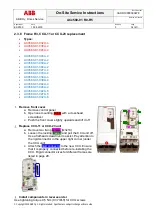
Remove front cover
a. Remove control panel
b. Open one mounting screw with a crosshead
screwdriver
c. Push the front cover slightly upwards and lift it off
Replace CCU-11 or CCU-23 unit
a. Remove two fixing screws (M3x10)
b. Loosen the locking
clamps
and pull the CCU unit off.
Use a flathead screwdriver to assist. Pay attention to
the rigid connector in the upper right corner (under
the CCU unit)
c. Attach the
rigid connector
to the new CCU. Ensure
that it is properly connected before re-installing the
CCU. Rigid connector sizes for different frames are
listed in page 29.
Install components in reverse order
Use tightening torque 0,5 Nm (0.37 lbf-ft) for CCU screws

