


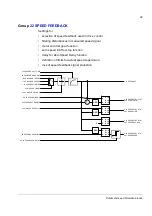
Parameters and firmware blocks
88
-11…11 V / -22…22 mA
Maximum AI2 input value.
13.08
AI2 MIN
FW block:
(see above)
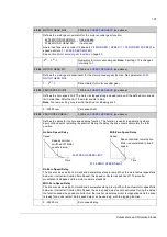
Defines the minimum value for analogue input AI2. The type is selected with jumper J2 on the JCU
Control Unit.
-11…11 V / -22…22 mA
Minimum AI2 input value.
13.09
AI2 MAX SCALE
FW block:
(see above)
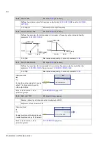
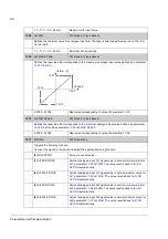
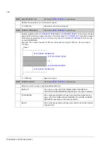
Defines the real value that corresponds to the maximum analogue input value defined by parameter
.
-32768…32768
Real value corresponding to value of parameter
13.10
AI2 MIN SCALE
FW block:
(see above)
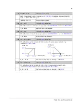
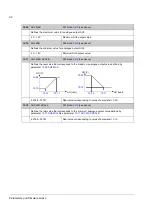
Defines the real value that corresponds to the minimum analogue input value defined by parameter
.
-32768…32768
Real value corresponding to value of parameter
13.11
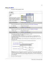
AITUNE
FW block: None
Triggers the AI tuning function.
Connect the signal to the input and select the appropriate tuning function.
(0)
NO ACTION
AI tune is not activated.
(1)
AI1 MIN TUNE
Current analogue input AI1 signal value is set as minimum value for
AI1, parameter
. The value reverts back to
automatically.
(2)
AI1 MAX TUNE
Current analogue input AI1 signal value is set as maximum value for
AI1, parameter
. The value reverts back to
automatically.
(3)
AI2 MIN TUNE
Current analogue input AI2 signal value is set as minimum value for
AI2, parameter
. The value reverts back to
automatically.
(4)
AI2 MAX TUNE
Current analogue input AI2 signal value is set as maximum value for
AI2, parameter
. The value reverts back to
automatically.
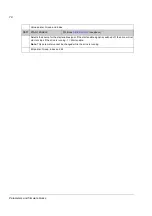
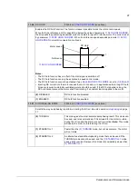
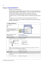
AI
(mA / V)
AI
(real)
Summary of Contents for ACSM1 Series
Page 1: ...ACSM1 Firmware Manual ACSM1 Speed and Torque Control Program...
Page 2: ......
Page 4: ......
Page 12: ...Table of contents 12...
Page 49: ...Drive control and features 49...
Page 282: ...Standard function blocks 282...
Page 306: ...Application program template 306...
Page 312: ...Control chain block diagrams 312...
Page 331: ...331...
Page 332: ...332...
Page 333: ......