Parameters and firmware blocks
156
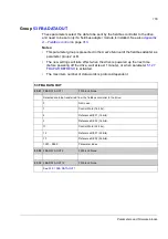
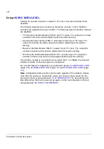
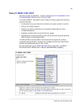
Group
Drive-to-drive communication settings. See
Appendix B – Drive-to-drive link
on page
57
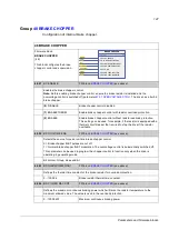
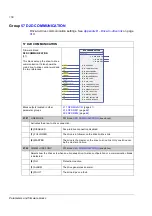
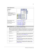
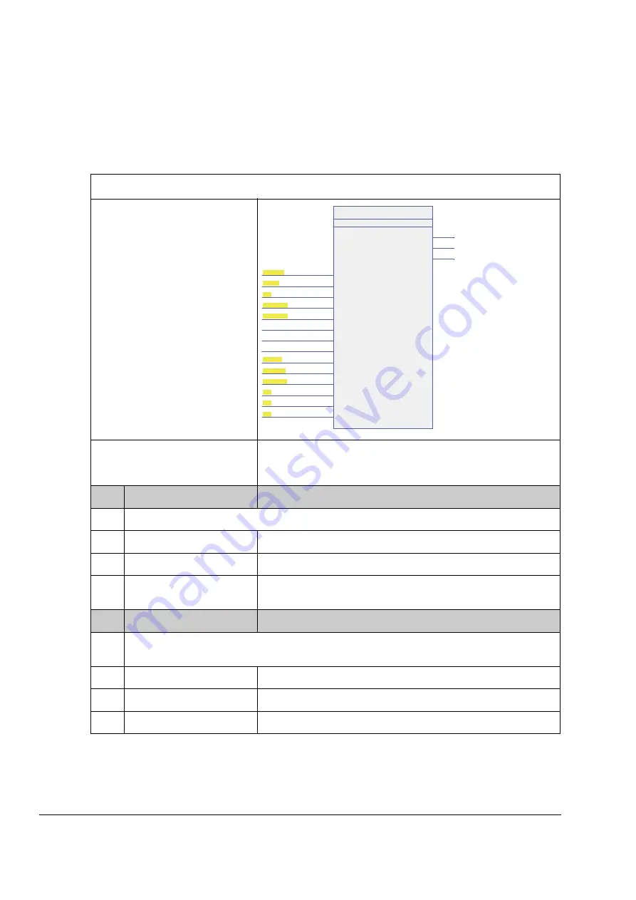
57 D2D COMMUNICATION
Firmware block:
D2D COMMUNICATION
(57)
This block sets up the drive-to-drive
communication. It also shows the
main drive-to-drive control word and
the two references.
Block outputs located in other
parameter groups
(page
(page
)
(page
)
57.01
LINK MODE
FW block:
(see above)
Activates the drive-to-drive connection.
(0)
DISABLED
Drive-to-drive connection disabled.
(1)
FOLLOWER
The drive is a follower on the drive-to-drive link.
(2)
MASTER
The drive is the master on the drive-to-drive link. Only one drive can
be the master at a time.
57.02
COMM LOSS FUNC
FW block:
(see above)
Selects how the drive acts when an erroneous drive-to-drive configuration or a communication break
is detected.
(0)
NO
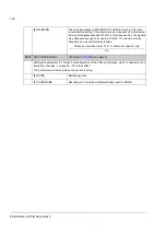
Protection inactive.
(1)
ALARM
The drive generates an alarm.
(2)
FAULT
The drive trips on a fault.
D2D COMMUNICATION
44
TLF9 500 μsec
(2)
57.01 LINK MODE
[ Disabled ]
57.02 COMM LOSS FUNC
[ Alarm ]
57.03 NODE ADDRESS
[ 1 ]
57.04 FOLLOWER MASK 1
[ 0000 0000 ]
57.05 FOLLOWER MASK 2
[ 0000 0000 ]
< 57.06 REF 1 SRC
[ SPEEDREF RAMPED ]
(6 / 3.04)
< 57.07 REF 2 SRC
[ TORQ REF TO TC ]
(8 / 3.13)
< 57.08 FOLLOWER CW SRC
[ D2D FOLLOWER CW ]
(4 / 2.18)
57.09 KERNEL SYNC MODE
[ NoSync ]
57.10 KERNEL SYNC OFFS
[ 0.000 ms ]
57.11 REF 1 MSG TYPE
[ Broadcast ]
57.12 REF1 MC GROUP
[ 0 ]
57.13 NEXT REF1 MC GRP
[ 0 ]
57.14 NR REF1 MC GRPS
[ 1 ]
2.17 D2D MAIN CW
2.19 D2D REF1
2.20 D2D REF2
Summary of Contents for ACSM1 Series
Page 1: ...ACSM1 Firmware Manual ACSM1 Speed and Torque Control Program...
Page 2: ......
Page 4: ......
Page 12: ...Table of contents 12...
Page 49: ...Drive control and features 49...
Page 282: ...Standard function blocks 282...
Page 306: ...Application program template 306...
Page 312: ...Control chain block diagrams 312...
Page 331: ...331...
Page 332: ...332...
Page 333: ......

