


•
■
Example
The example below shows how to configure parameters for cyclic correction.
•
=
•
= 1
•
= 1
•
= 1
•
86.17 Feed constant denominator
= 1
•
= 1
•
86.19 Modulo range denominator
= 1
•
= Bit 0
•
= Bit 1
•
= Bit 0
•
= 0.00
•
78.10 Cyclic correction enable
=
•
= 0.000
•
= 0.000
•
= 0.000
•
= 10000.000
•
78.15 Maximum single correction
= 10000.000
•
= 1.000
•
75.42 Superimposed acceleration
= 10.000
•
75.43 Superimposed deceleration
= 10.000
•
= 0.000
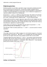
The figure below explains the drive behavior with corrective actions.
•
Master runs forward in speed mode at low speed.
•
Follower starts at a random moment and with gear-in function.
•
Follower ramps to master speed but phase shift between drives occurs.
•
Receives first master latch (cursor 1) at the position of 0.307 revolutions.
•
Receives axis latch (cursor 2) at 0.765 revolutions.
58 Position control program features
Summary of Contents for ACS880 N5700 Series
Page 1: ... ABB INDUSTRIAL DRIVES ACS880 position control program N5700 Firmware manual ...
Page 2: ......
Page 4: ......
Page 22: ...22 ...
Page 28: ...28 ...
Page 32: ...32 ...
Page 60: ...60 ...
Page 546: ...546 ...
Page 604: ...604 ...
Page 626: ...626 ...
Page 640: ...640 ...
Page 660: ...660 ...