Tasks
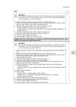
WARNING!
When you start the supply unit, the drive DC bus will be energized, as will all the units connec-
ted to the DC bus. If you want to prevent this for any of the units, open its DC switch/discon-
nector (if available), or remove its DC fuses.
1. Make sure that DC switch/disconnector [Q11] is open. Indicator [P13] is on.
2. Start the drive supply unit and energize the drive: Use operating switch [S21] on the door of the
drive incoming cubicle. See the supply unit hardware manual.
3. Make sure that energy storage is ready for the connection to the drive.
•Energy storage disconnector is open. Indicator [P12] is on.
•Energy storage control system has released the DC switch/disconnector [Q11] interlocking. In-
dicator [P11] is on.
4. Close the DC switch/disconnector [Q11]. Indicator [P13] goes off.
5. Close the energy storage disconnector. Indicator [P12] goes off.
6. Close the energy storage circuit breaker.
The energy storage is connected to the drive DC link.
Energizing the drive and DC feeder unit - DC feeder unit with DC switch/disconnector ([Q11], option
+F290) and charging switch ([Q10] F272)
WARNING!
When you start the supply unit, the drive DC bus will be energized, as will all the units connec-
ted to the DC bus. If you want to prevent this for any of the units, open its DC switch/discon-
nector (if available), or remove its DC fuses.
1. Make sure that DC switch/disconnector [Q11] and charging switch [Q10] are open. Indicator [P13]
is on.
2. Make sure that the energy storage disconnector is open. Indicator [P12] is on.
3. Start the drive supply unit and energize the drive. Use operating switch [S21] on the door of the
drive incoming cubicle. See the supply unit hardware manual.
4. Close charging switch [Q10].
5. Close the energy storage disconnector. Indicator [P12] goes off.
6. Close the energy storage circuit breaker. The charging starts.
7. Wait for the completion of the charging. See the documentation of the energy storage control
system (customer-defined) for the indication.
8. After the charging is completed, open the energy storage circuit breaker and disconnector.
•Indicator [P12] is on.
•Energy storage control system releases the DC switch/disconnector [Q11] interlocking. Indicator
[P11] is on.
9. Open charging switch [Q10].
10. Make sure that:
•Indicator [P12] is on. (Energy storage is disconnected.)
•Indicator [P11] is on. (DC switch/disconnector [Q11] interlocking is not energized.)
•Charging switch [Q10] is open.
11. Close DC switch/disconnector [Q11]. Indicator [P13] goes off.
12. Close the energy storage disconnector. Indicator [P12] goes off.
13. Close the energy storage circuit breaker.
The energy storage is charged and connected to the drive DC link.
Start-up 39
12
Summary of Contents for ACS880-7107LC DC
Page 1: ... ABB INDUSTRIAL DRIVES ACS880 7107LC DC feeder unit Hardware manual ...
Page 2: ......
Page 4: ......
Page 8: ...8 ...
Page 12: ...12 ...
Page 22: ...22 ...
Page 36: ...36 ...
Page 40: ...40 ...
Page 44: ...44 ...
Page 50: ...50 ...
Page 52: ...52 ...
Page 55: ...Terminal and cable entry data for the power cables Technical data 55 ...

