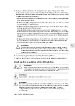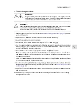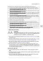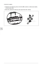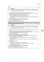
1. Make sure that the cable is disconnected both at the drive end and at the other end: all
conductors (including the grounding conductor) and the cable shield.
2. At the drive end, connect all conductors and shield of the cable together and to the
grounding busbar (PE).
3. Disconnect one conductor and measure the insulation resistance between the conductor
and the PE by using a measuring voltage of 1 kV DC. The insulation resistance must
be higher than 1 Mohm.
4. Reconnect the conductor, disconnect another conductor and measure its insulation
resistance. Repeat this for all remaining conductors (including the cable shield).
-
+
Ohm
ES+
ES-
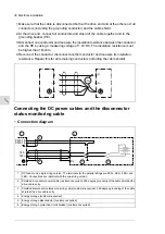
Connecting the DC power cables and the disconnector
status monitoring cable
■
Connection diagram
1ES-
1ES+
X350.16
X350.14
1
3
2
4
5
6
DC feeder unit, single string version. The terminals for the parallel strings are 2ES+, 2ES-, 3ES+ and
3ES-. Connections are identical with the one-string version.
1
Shielded 4-conductor power cable (customer-acquired). 360 degree grounding of the cable shield at the
drive cable entry.
2
Shielded disconnector status monitoring cable (customer-acquired). 360 degree grounding of the cable
shield at the drive cable entry.
3
Energy storage (customer-acquired)
4
Energy storage disconnector (customer-acquired)
5
Energy storage protective circuit breaker (customer-acquired)
6
30 Electrical installation
Summary of Contents for ACS880-7107LC DC
Page 1: ... ABB INDUSTRIAL DRIVES ACS880 7107LC DC feeder unit Hardware manual ...
Page 2: ......
Page 4: ......
Page 8: ...8 ...
Page 12: ...12 ...
Page 22: ...22 ...
Page 36: ...36 ...
Page 40: ...40 ...
Page 44: ...44 ...
Page 50: ...50 ...
Page 52: ...52 ...
Page 55: ...Terminal and cable entry data for the power cables Technical data 55 ...

