■
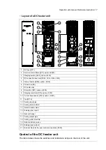
Layout of a DC feeder unit
1
8
9
10
11
12
16
17
18
19
20
21
13
14
15
2
3
4
5
6
7
DC fuses [F11]
1
Common mode filters ([R11], E208)
2
Charging switch ([Q10], F272)
3
DC connection bus bars [1ES+, 1ES-, 2ES+, 2ES-]
4
Cabinet heater ([E95], G300)
5
PE bus bar [PE]
6
DC cable entry
7
DC switch ([Q11], F290)
8
Charging resistors ([R10], F272)
9
Current transducers ([T353], G353)
10
Fan [G115]
11
Cooling input pipe
12
Cooling inlet manifold
13
Inlet and drain valves
14
Draining pipe (input)
15
Heat exchanger
16
Cooling output pipe
17
Cooling outlet manifold
18
Outlet and drain valves
19
Draining pipe (output)
20
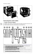
Terminal block for the user control connections [X350]
21
Control of the DC feeder unit
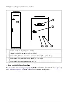
The table below shows the switches and indications lamps on the door of the unit.
Operation principle and hardware description 17
Summary of Contents for ACS880-7107LC DC
Page 1: ... ABB INDUSTRIAL DRIVES ACS880 7107LC DC feeder unit Hardware manual ...
Page 2: ......
Page 4: ......
Page 8: ...8 ...
Page 12: ...12 ...
Page 22: ...22 ...
Page 36: ...36 ...
Page 40: ...40 ...
Page 44: ...44 ...
Page 50: ...50 ...
Page 52: ...52 ...
Page 55: ...Terminal and cable entry data for the power cables Technical data 55 ...

