


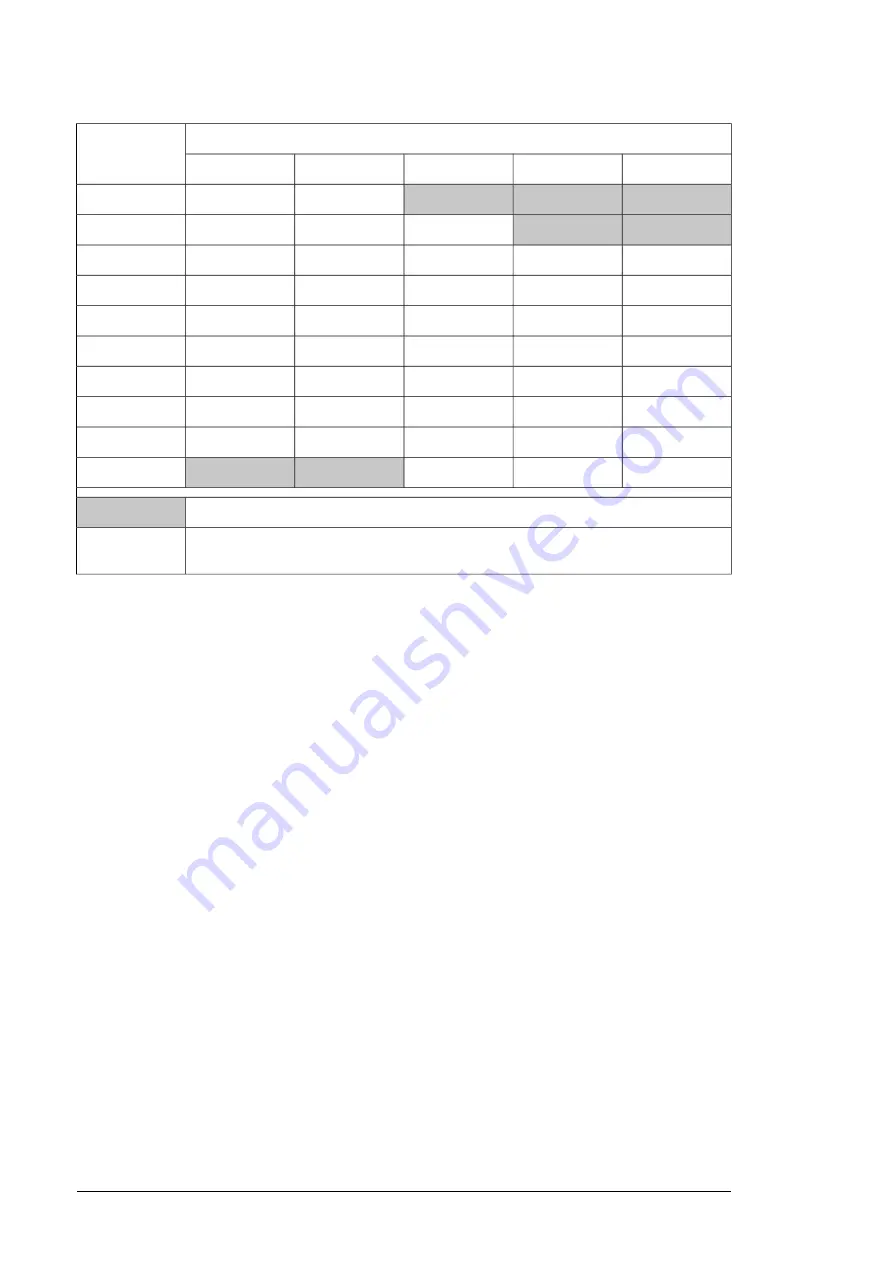
Min. T
coolant
(°C)
T
air
(°C)
RH = 40%
RH = 50%
RH = 65%
RH = 80%
RH = 95%
-3.0
-0.1
3.7
6.7
9.2
10
1.5
4.6
8.4
11.5
14.2
15
6.0
9.4
13.2
16.5
19.2
20
10.5
13.8
17.9
21.4
24.1
25
15.0
18.4
22.7
26.2
29.1
30
19.4
23.0
27.4
31.1
34.1
35
23.8
27.6
32.2
35.9
39.0
40
28.2
32.1
36.8
40.8
44.0
45
32.8
36.7
41.6
45.6
49.0
50
37.1
42.2
46.3
50.4
53.9
55
= Not allowed as standard but the coolant temperature must be 0 °C (32 °F) or above.
At an air temperature of 45 °C and relative humidity of 65% the coolant temperature may
not be below +36.8 °C
Example:
Maximum temperature rise:
Depends on heat losses and mass flow. Typically 10 °C (18
°F) with nominal losses and flow.
■
Pressure limits
Base pressure:
100 … 150 kPa (recommended); 200 kPa (maximum). “Base pressure”
denotes the pressure of the system compared with the atmospheric pressure when the
cooling circuit is filled with coolant.
Air counterpressure in the expansion tank:
40 kPa
Design pressure (PS):
600 kPa
Nominal pressure difference
(between main in/out lines): 120 kPa with 25/75% (volume)
coolant solution, 150 kPa with 50/50% (volume) coolant solution. This has to be taken into
account when dimensioning the liquid cooling circuit.
Maximum pressure difference
(between main in/out lines): 200 kPa
■
Coolant flow rate limits
The maximum coolant flow rate for all drive equipment is 1.3 × nominal. See the technical
data chapter for nominal values.
■
Cooling circuit materials
Materials used in the internal cooling circuit are listed below. These are also the only materials
that can be used in the external cooling circuit.
•
stainless steel AISI 316L (UNS 31603)
•
heavy gauge aluminum
•
plastic materials such as PA, PEX and PTFE
Note:
PVC hoses are not suitable for use with antifreeze.
178 Internal cooling circuit
Summary of Contents for ACS880-204LC
Page 1: ... ABB INDUSTRIAL DRIVES ACS880 204LC IGBT supply modules Hardware manual ...
Page 2: ......
Page 4: ......
Page 16: ...16 ...
Page 32: ...32 ...
Page 39: ...Overview of kits Cabinet construction 39 ...
Page 40: ...Stage 1 Installation of common parts 40 Cabinet construction ...
Page 41: ...Stage 2 Installation of LCL side plates and common AC bus Cabinet construction 41 ...
Page 42: ...Stage 3 Installation of brackets for Flat PLS holder 42 Cabinet construction ...
Page 43: ...Stage 4A BLCL 15LC 7 AC connection and fuse busbars installation Cabinet construction 43 ...
Page 44: ...Stage 4B BLCL 24LC 7 AC connection and fuse busbars installation 44 Cabinet construction ...
Page 46: ...Stage 6 LCL choke and LCL choke busbar installation 46 Cabinet construction ...
Page 50: ...Stage 9 Installation of LCL shroud kit 50 Cabinet construction ...
Page 52: ...Overview of kits 52 Cabinet construction ...
Page 53: ...Stage 1 Installation of common parts Cabinet construction 53 ...
Page 54: ...Stage 2 Installation of LCL side plates and common AC bus 54 Cabinet construction ...
Page 55: ...Stage 3 Installation of brackets for Flat PLS holder Cabinet construction 55 ...
Page 56: ...Stage 4 AC connection and fuse busbars installation 56 Cabinet construction ...
Page 58: ...Stage 6 LCL choke and LCL choke busbar installation 58 Cabinet construction ...
Page 61: ...Stage 9 Installation of LCL shroud kit Cabinet construction 61 ...
Page 65: ...Overview of kits Cabinet construction 65 ...
Page 66: ...Stage 1 Installation of common parts 66 Cabinet construction ...
Page 67: ...Stage 2 Side plate module mounting mechanics and quick connectors Cabinet construction 67 ...
Page 68: ...Stage 3 Flat PLS support kit for AC and common AC connection busbars 68 Cabinet construction ...
Page 69: ...Stage 4 Fan heat exchanger and cooling components Cabinet construction 69 ...
Page 70: ...Stage 5A Installation of DC busbars 70 Cabinet construction ...
Page 72: ...Stage 6 Module installation 72 Cabinet construction ...
Page 73: ...Stage 7 Installation of shrouding Cabinet construction 73 ...
Page 77: ...Overview of kits Cabinet construction 77 ...
Page 78: ...Stage 1 Installation of common parts 78 Cabinet construction ...
Page 79: ...Stage 2 Side plate module mounting mechanics and quick connectors Cabinet construction 79 ...
Page 80: ...Stage 3 Flat PLS support kit for AC and common AC connection busbars 80 Cabinet construction ...
Page 81: ...Stage 4 Fan heat exchanger and cooling components Cabinet construction 81 ...
Page 82: ...Stage 5A Installation of DC busbars 82 Cabinet construction ...
Page 84: ...Stage 6 Module installation 84 Cabinet construction ...
Page 85: ...Stage 7 Installation of shrouding Cabinet construction 85 ...
Page 89: ...Overview of kits Cabinet construction 89 ...
Page 90: ...Stage 1 Installation of common parts 90 Cabinet construction ...
Page 91: ...Stage 2 Side plate module mounting mechanics and quick connectors Cabinet construction 91 ...
Page 92: ...Stage 3 Flat PLS support kit for AC and common AC connection busbars 92 Cabinet construction ...
Page 93: ...Stage 4 Fan heat exchanger and cooling components Cabinet construction 93 ...
Page 94: ...Stage 5A Installation of DC busbars 94 Cabinet construction ...
Page 96: ...Stage 6 Module installation 96 Cabinet construction ...
Page 97: ...Stage 7 Installation of shrouding Cabinet construction 97 ...
Page 98: ...98 ...
Page 114: ...114 ...
Page 125: ...a b c Maintenance 125 ...
Page 180: ...180 ...
Page 206: ...206 ...
Page 208: ...Frame R8i module 208 Dimension drawings ...
Page 209: ... Quick connector Dimension drawings 209 ...
Page 210: ...LCL filter components Grid side choke BLCL 15LC 7 and BLCL 24LC 7 210 Dimension drawings ...
Page 211: ... Grid side choke BLCL 25LC 7 Dimension drawings 211 ...
Page 212: ... Converter side choke BLCL 15LC 7 and BLCL 24LC 7 212 Dimension drawings ...
Page 213: ... Converter side choke BLCL 25LC 7 Dimension drawings 213 ...
Page 214: ... Capacitor www tdk electronics tdk com 214 Dimension drawings ...
Page 276: ...276 ...


