


3.
Push the module up the ramp and back into the cubicle.
•
Keep your fingers away from the edge of the module front plate to avoid
pinching.
•
Keep a constant pressure with one foot on the base of the module to prevent
the module from falling on its back.
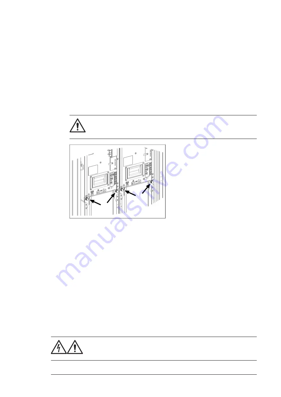
4.
Secure the top front of the module with two screws. Tighten to 22 N·m (16 lbf·ft).
5.
Secure the bottom front of the module with two screws. Tighten to 22 N·m (16 lbf·ft).
6.
Remove the ramp.
7.
Drives with C121 (Marine construction) or +C180 (Seismic design):
a.
Remove the bolts holding the fan carriage (two bolts per module).
WARNING!
The module retaining screws (two at top, two at bottom per
module) must be in place before removing these screws. Otherwise, the
parts of the module can become separated and cause injury or damage.
b.
Reinstall the transverse retaining bracket. At the ends of the bracket, tighten the
screws to 9 N·m [6.6 lbf·ft]. Reinstall the fan carriage bolts removed at previous
step, and tighten to 22 N·m (16 lbf·ft).
8.
Attach the DC busbars to the module. Tighten to 70 N·m (52 lbf·ft).
9.
Reconnect terminal block [X50] at the top of the module.
10. Reconnect the wiring and fiber optic cables to the terminals on the front of the module.
11. Repeat the procedure for the other inverter modules.
12. Reinstall the shroud near the top of the cubicle.
Activating the reduced run of the inverter unit
A “reduced run” function is available for inverter units consisting of parallel-connected inverter
modules. The function makes it possible to continue operation with limited current even if
one (or more) module is out of service, for example, because of maintenance work. In
principle, reduced run is possible with only one module, but the physical requirements of
operating the motor still apply; for example, the modules remaining in use must be able to
provide the motor with enough magnetizing current.
WARNING!
Read the safety instructions. If you ignore them, injury or death, or damage
to the equipment can occur.
Maintenance 123
Summary of Contents for ACS880-107
Page 1: ... ABB INDUSTRIAL DRIVES ACS880 107 inverter units Hardware manual ...
Page 2: ......
Page 4: ......
Page 10: ...10 ...
Page 64: ...2 4 5 6 7 8 11 10 3 a b a b b 1 5 a 64 Electrical installation ...
Page 69: ...Electrical installation 109 5 6 4 3 Electrical installation 69 11 ...
Page 70: ...7 a b d c 110 Electrical installation 7 8 8 8 9 9 70 Electrical installation ...
Page 75: ...2 11 b PE 10 7 5 6 8 a 360 grounding detail Electrical installation 75 11 ...
Page 89: ...With FDPI 02 modules OPEN TERMIN ATED 1 1 2 2 OPEN TERMINATED 3 Electrical installation 89 11 ...
Page 90: ...90 ...
Page 96: ...96 ...
Page 110: ...4 5 6 7 8 6 10 10 110 Maintenance ...
Page 118: ...2 3 7 9 a a c c c 6 8 b b d d 11 e e 118 Maintenance ...
Page 121: ...7 a b d c 110 Electrical installation 7 8 8 8 9 9 Maintenance 121 ...
Page 130: ...130 ...
Page 154: ...154 ...
Page 155: ...Circuit diagrams Refer to the circuit diagrams delivered with the unit 9 Circuit diagrams 155 ...
Page 156: ...156 ...
Page 159: ... Dimension drawing 400 mm wide cubicle R1i R4i 400 mm R6i R7i Dimensions and weights 159 ...
Page 161: ... Dimension drawing R8i without C128 or H353 bottom cable exit Dimensions and weights 161 ...
Page 162: ... Dimension drawing R8i without C128 or H353 top cable exit 162 Dimensions and weights ...
Page 163: ... Dimension drawing 2 R8i without C128 or H353 bottom cable exit Dimensions and weights 163 ...
Page 164: ... Dimension drawing 2 R8i without C128 or H353 top cable exit 164 Dimensions and weights ...
Page 165: ... Dimension drawing 3 R8i without C128 or H353 bottom cable exit Dimensions and weights 165 ...
Page 166: ... Dimension drawing 3 R8i without C128 or H353 top cable exit 166 Dimensions and weights ...
Page 167: ... Dimension drawing drive control unit DCU 300 mm Dimensions and weights 167 ...
Page 169: ...Inverter module cubicle with one R8i module top cable exit Dimensions and weights 169 ...
Page 182: ...182 ...
Page 200: ...200 ...


