88 Electrical installation
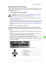
Connection procedure
WARNING!
Obey the instructions in chapter
ignore them, injury or death, or damage to the equipment can occur.
1. Do the steps in section
Precautions before electrical work
before you start the work.
2. Open the door of the incoming cubicle (ICU).
3. Remove the shrouding covering the input terminals.
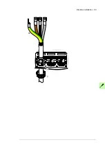
4. Peel off 3 to 5 cm of the outer insulation of the cables above the lead-through plate for
360° high-frequency grounding.
5. Prepare the ends of the cables.
6. If fire insulation is used, make an opening in the mineral wool sheet according to the
diameter of the cable.
7. For IP22, IP42 drives: Slide the cables through the lead-throughs with the conductive
sleeves.
8. For IP54 drives: Remove the rubber grommets from the lead-through plate for the
cables to be connected. Cut adequate holes into the rubber grommets. Slide the
grommets onto the cables. Slide the cables through the lead-throughs with the
conductive sleeves and attach the grommets to the holes.
9. Fasten the conductive sleeves to the cable shields with cable ties.
10. Seal the slot between the cable and mineral wool sheet (if used) with sealing
compound.
11. Tie up the unused conductive sleeves with cable ties.
12. Connect the twisted shields of the cables to the PE busbar of the cabinet.
13. Connect the phase conductors of the input cable to the L1, L2 and L3 terminals. (With
12-pulse connection, the terminals are 1L1, 1L2 and 1L3 for one 6-pulse supply line,
2L1, 2L2 and 2L3 for the other.).
14. Reinstall the shrouding removed earlier.
15. Close the door.
PE
PE
5
5
Summary of Contents for ACS880-07XT Series
Page 1: ...ABB industrial drives Hardware manual ACS880 07XT drives 400 to 1200 kW ...
Page 4: ......
Page 12: ...12 ...
Page 20: ...20 Safety instructions ...
Page 26: ...26 Introduction to the manual ...
Page 54: ...54 Mechanical installation ...
Page 89: ...Electrical installation 89 PE 11 8 4 9 11 ...
Page 94: ...94 Electrical installation ...
Page 112: ...112 Fault tracing ...
Page 123: ...Maintenance 123 5 6 7 ...
Page 124: ...124 Maintenance 8 10 9 ...
Page 126: ...126 Maintenance 6 5 4 ...
Page 127: ...Maintenance 127 9 8 7 ...
Page 128: ...128 Maintenance 12 11 10 ...
Page 149: ...Dimensions 149 Dimension drawing examples Frame 2 R11 R10 with brake chopper ...
Page 150: ...150 Dimensions Frame 2 R11 R10 without brake chopper ...
Page 153: ...Dimensions 153 Location of input terminals ACS880 07XT 12 pulse ...
Page 154: ...154 Dimensions Location of output terminals ACS880 07XT R10 with du dt ...
Page 155: ...Dimensions 155 Location of output terminals ACS880 07XT R10 without du dt ...
Page 156: ...156 Dimensions Location of output terminals ACS880 07XT R11 with du dt ...
Page 157: ...Dimensions 157 Location of output terminals ACS880 07XT R11 without du dt ...
Page 158: ...158 Dimensions Location of PE terminals ACS880 07XT ...
Page 159: ...Dimensions 159 Location of resistor terminals ACS880 07XT R10 ...
Page 160: ...160 Dimensions Location of resistor terminals ACS880 07XT R11 ...
Page 168: ...www abb com drives www abb com drivespartners 3ABD00043579 Rev C EN 2018 01 01 Contact us ...


