Start-up 109
Setting up the supply unit parameters
Check the voltage range setting in parameter
195.01 Supply voltage.
Setting up the Main Fan fault parameters
Check the 31.35 Main Fan Fault Function = Fault for better protection of cabinet.
Setting up the drive parameters, and performing the first start
Set up the inverter control program. See the appropriate start-up guide and/or firmware manual.
There is a separate start-up guide only for some control programs.
If you need more information on the use of the control panel, see
ACS-AP-X Assistant control panels
user's manual
(3AUA0000085685 [English]).
Drives with a brake chopper (D150): Refer also to chapter
Drives with an fieldbus adapter module (optional): Set the fieldbus parameters. Activate the
appropriate assistant in the control program, or see the user’s manual of the fieldbus adapter module,
and the drive firmware manual. Not all control programs include assistants.
Check that the communication works between the drive and the PLC.
Drives with an encoder interface module (optional): Set the encoder parameters. Activate the
appropriate assistant in the control program, or see the user’s manual of the encoder interface
module, and the drive firmware manual. Not all control programs include assistants.
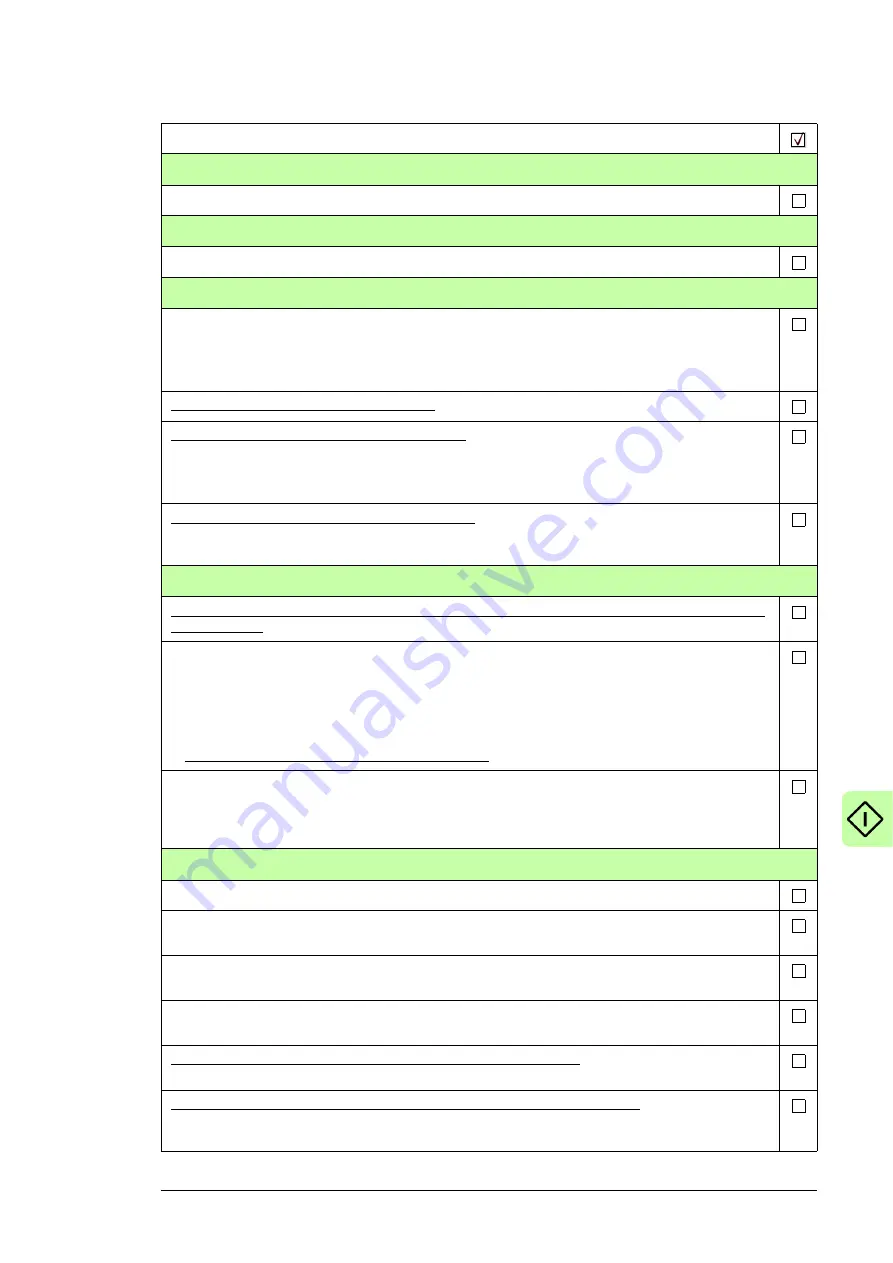
Powering up the main circuit of the drive
Switch the grounding switch (Q9.1) (F259) off. 12-pulse units have two grounding switches,
Q9.1 and Q9.2.
Close the main switch-disconnector (Q1.1) or main breaker (Q1).
Note:
Do not use excessive force. The main switch-disconnector (or main breaker) can only be
closed when
• the main input terminals (L1, L2, L3) are powered, and
• auxiliary voltage is switched on (Q21, if present), and
• grounding switch is off (Q9.1, Q9.2) (F259).
Turn the operating switch (S21) to the ON (1) position to activate the run enable signal. Depending on
control source settings, this may also close the main contactor (if present). If a main contactor is
present and does not close, refer to the circuit diagrams delivered by the drive as well as the
appropriate firmware manuals.
On-load checks
Start the motor to perform the ID run.
Check that the cooling fans rotate freely in the right direction, and the air flows upwards. A paper
sheet set on the intake (door) gratings stays. The fans run noiselessly.
Check that the motor starts. stops and follows the speed reference in the correct direction when
controlled with the control panel.
Check that the motor starts. stops and follows the speed reference in the correct direction when
controlled through the customer-specific I/O or fieldbus.
Drives in which the Safe torque off control circuit is connected in use: Test and validate the operation
of the Safe torque off function.
Drives with an emergency stop circuit (oQ951, +Q952, +Q963, +Q964): Test and validate the
operation of the emergency-stop circuit. See the delivery specific circuit diagrams and wiring, start-up
and operating instructions of the option.
Action
Summary of Contents for ACS880-07XT Series
Page 1: ...ABB industrial drives Hardware manual ACS880 07XT drives 400 to 1200 kW ...
Page 4: ......
Page 12: ...12 ...
Page 20: ...20 Safety instructions ...
Page 26: ...26 Introduction to the manual ...
Page 54: ...54 Mechanical installation ...
Page 89: ...Electrical installation 89 PE 11 8 4 9 11 ...
Page 94: ...94 Electrical installation ...
Page 112: ...112 Fault tracing ...
Page 123: ...Maintenance 123 5 6 7 ...
Page 124: ...124 Maintenance 8 10 9 ...
Page 126: ...126 Maintenance 6 5 4 ...
Page 127: ...Maintenance 127 9 8 7 ...
Page 128: ...128 Maintenance 12 11 10 ...
Page 149: ...Dimensions 149 Dimension drawing examples Frame 2 R11 R10 with brake chopper ...
Page 150: ...150 Dimensions Frame 2 R11 R10 without brake chopper ...
Page 153: ...Dimensions 153 Location of input terminals ACS880 07XT 12 pulse ...
Page 154: ...154 Dimensions Location of output terminals ACS880 07XT R10 with du dt ...
Page 155: ...Dimensions 155 Location of output terminals ACS880 07XT R10 without du dt ...
Page 156: ...156 Dimensions Location of output terminals ACS880 07XT R11 with du dt ...
Page 157: ...Dimensions 157 Location of output terminals ACS880 07XT R11 without du dt ...
Page 158: ...158 Dimensions Location of PE terminals ACS880 07XT ...
Page 159: ...Dimensions 159 Location of resistor terminals ACS880 07XT R10 ...
Page 160: ...160 Dimensions Location of resistor terminals ACS880 07XT R11 ...
Page 168: ...www abb com drives www abb com drivespartners 3ABD00043579 Rev C EN 2018 01 01 Contact us ...


