


108 Start-up
Action
Safety
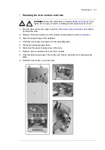
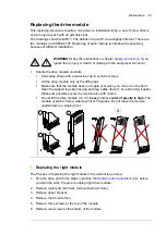
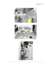
WARNING!
Obey the safety instructions during the start-up procedure. See chapter
Checks/Settings with no voltage connected
Ensure that the disconnector of the supply transformer is locked to the off (0) position, ie. no voltage
is, and cannot be connected to the drive inadvertently.
Check that the main switch-disconnector (Q1.1) is switched off, or main breaker (Q1) racked out.
Note:
Some 12-pulse units are equipped with two switch-disconnectors or breakers – check that both
are open before you proceed.
Check that the grounding switch (Q9.1) (F259) is switched on. 12-pulse units have two
switches, Q9.1 and Q9.2.
Check the mechanical and electrical installation of the drive. See
Check the settings of breakers/switches in the auxiliary circuits. See the circuit diagrams delivered
with the drive.
Disconnect any unfinished or uninspected auxiliary voltage (115/230 V AC) cables that lead from the
terminal blocks to the outside of the equipment.
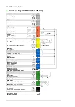
Check that both channels of the Safe torque off circuit connected to the STO inputs of control unit
[A41] are closed. Refer to the wiring diagrams delivered with the drive.
If the Safe torque off functionality is used, check that the STO OUT output on the inverter control unit
(A41) is chained to the STO inputs of all modules.
If the Safe torque off functionality is not used, check that the STO input on all inverter modules is
correctly wired to +24 V and ground.
Drives with ground fault monitoring for IT (ungrounded) systems (Q954): Adjust the settings
of the ground fault monitor to suit the installation. See the circuit diagrams of the delivery and
IRDH275B Ground Fault Monitor Operating Manual
by Bender (code: TGH1386en).
Drives with Pt100 relays ((n)L506):
• Check the connections against the circuit diagrams of the delivery.
• Set the alarm and trip levels of the Pt100 relays.
Set the alarm and trip levels of the Pt100 relay as low as possible based on the operating
temperature and test results of the machine. The trip level can be set, for example, 10 °C higher than
what the temperature of the machine is at maximal load in the maximum environmental temperature.
We recommend to set the operating temperatures of the relay, typically for example, as follows:
• 120…140 °C when only tripping is in use
• alarm 120…140 °C and trip 130…150 °C when both alarm and tripping are used.
Powering up the auxiliary circuit of the drive
Make sure that it is safe to connect voltage. Ensure that
• nobody is working on the drive or circuits that have been wired from outside into the drive cabinet
• the cover of the motor terminal box is in place.
Close the circuit breakers supplying the auxiliary circuits.
Close the cabinet doors.
Close the main breaker of the supply transformer.
Switch on the auxiliary voltage (Q21,if present).
Summary of Contents for ACS880-07XT Series
Page 1: ...ABB industrial drives Hardware manual ACS880 07XT drives 400 to 1200 kW ...
Page 4: ......
Page 12: ...12 ...
Page 20: ...20 Safety instructions ...
Page 26: ...26 Introduction to the manual ...
Page 54: ...54 Mechanical installation ...
Page 89: ...Electrical installation 89 PE 11 8 4 9 11 ...
Page 94: ...94 Electrical installation ...
Page 112: ...112 Fault tracing ...
Page 123: ...Maintenance 123 5 6 7 ...
Page 124: ...124 Maintenance 8 10 9 ...
Page 126: ...126 Maintenance 6 5 4 ...
Page 127: ...Maintenance 127 9 8 7 ...
Page 128: ...128 Maintenance 12 11 10 ...
Page 149: ...Dimensions 149 Dimension drawing examples Frame 2 R11 R10 with brake chopper ...
Page 150: ...150 Dimensions Frame 2 R11 R10 without brake chopper ...
Page 153: ...Dimensions 153 Location of input terminals ACS880 07XT 12 pulse ...
Page 154: ...154 Dimensions Location of output terminals ACS880 07XT R10 with du dt ...
Page 155: ...Dimensions 155 Location of output terminals ACS880 07XT R10 without du dt ...
Page 156: ...156 Dimensions Location of output terminals ACS880 07XT R11 with du dt ...
Page 157: ...Dimensions 157 Location of output terminals ACS880 07XT R11 without du dt ...
Page 158: ...158 Dimensions Location of PE terminals ACS880 07XT ...
Page 159: ...Dimensions 159 Location of resistor terminals ACS880 07XT R10 ...
Page 160: ...160 Dimensions Location of resistor terminals ACS880 07XT R11 ...
Page 168: ...www abb com drives www abb com drivespartners 3ABD00043579 Rev C EN 2018 01 01 Contact us ...