


■
T111 tap settings
96 Electrical installation
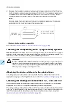
T111 tap settings
3~ input
3~ output
Supply
voltage
Terminals
Tap settings
Terminals
A1–
B1–
C1–
400 V
(50 Hz)
320/340 V
(60 Hz)
690 V
A1, B1, C1
C2
A2
B2
a1, b1, c1
a2, b2, c2
660 V
A1, B1, C1
C2
A2
B2
a1, b1, c1
a2, b2, c2
600 V
A1, B1, C1
C3
A3
B3
a1, b1, c1
a2, b2, c2
575 V
A1, B1, C1
C3
A3
B3
a1, b1, c1
a2, b2, c2
540 V
A1, B1, C1
C4
A4
B4
a1, b1, c1
a2, b2, c2
525 V
A1, B1, C1
C4
A4
B4
a1, b1, c1
a2, b2, c2
500 V
A1, B1, C1
C4
A4
B4
a1, b1, c1
a2, b2, c2
480 V
A1, B1, C1
C5
A5
B5
a1, b1, c1
a2, b2, c2
460 V
A1, B1, C1
C5
A5
B5
a1, b1, c1
a2, b2, c2
440 V
A1, B1, C1
C5
A5
B5
a1, b1, c1
a2, b2, c2
415 V
A1, B1, C1
C6
A6
B6
a1, b1, c1
a2, b2, c2
400 V
A1, B1, C1
C6
A6
B6
a1, b1, c1
a2, b2, c2
380 V
A1, B1, C1
C6
A6
B6
a1, b1, c1
a2, b2, c2
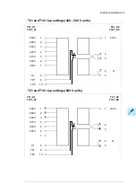
3~ input
3~ output
3~ output
3~ input
Terminals
Tap settings
Terminals
Supply voltage
320/340 V
(60 Hz)
400 V
(50 Hz)
C1–
B1–
A1–
a2, b2, c2
a1, b1, c1
B2
A2
C2
A1, B1, C1
690 V
a2, b2, c2
a1, b1, c1
B2
A2
C2
A1, B1, C1
660 V
a2, b2, c2
a1, b1, c1
B3
A3
C3
A1, B1, C1
600 V
a2, b2, c2
a1, b1, c1
B3
A3
C3
A1, B1, C1
575 V
a2, b2, c2
a1, b1, c1
B4
A4
C4
A1, B1, C1
540 V
a2, b2, c2
a1, b1, c1
B4
A4
C4
A1, B1, C1
525 V
a2, b2, c2
a1, b1, c1
B4
A4
C4
A1, B1, C1
500 V
a2, b2, c2
a1, b1, c1
B5
A5
C5
A1, B1, C1
480 V
a2, b2, c2
a1, b1, c1
B5
A5
C5
A1, B1, C1
460 V
a2, b2, c2
a1, b1, c1
B5
A5
C5
A1, B1, C1
440 V
a2, b2, c2
a1, b1, c1
B6
A6
C6
A1, B1, C1
415 V
a2, b2, c2
a1, b1, c1
B6
A6
C6
A1, B1, C1
400 V
a2, b2, c2
a1, b1, c1
B6
A6
C6
A1, B1, C1
380 V
98 Electrical installation
Summary of Contents for ACS880-07
Page 1: ...ABB industrial drives Hardware manual ACS880 07 drives 560 to 2800 kW ...
Page 2: ......
Page 4: ......
Page 22: ...22 ...
Page 28: ...28 ...
Page 94: ...94 ...
Page 112: ...Electrical installation 109 5 6 4 3 112 Electrical installation ...
Page 113: ...110 Electrical installation 7 8 8 Electrical installation 113 ...
Page 114: ...Electrical installation 111 9 10 114 Electrical installation ...
Page 116: ...Electrical installation 113 4 5 3 6 7 116 Electrical installation ...
Page 118: ...2 11 b PE 10 7 5 6 8 a 360 grounding detail 118 Electrical installation ...
Page 128: ...128 ...
Page 146: ...146 ...
Page 148: ...148 ...
Page 159: ...12 Install and tighten the two M4 12 T20 screws 10 11 12 Maintenance 159 ...
Page 162: ...6 6a 6a 6b 7a 7b 7 8 8a 8b 162 Maintenance ...
Page 166: ...166 Maintenance 6 6 7 8 7 166 Maintenance ...
Page 173: ...6 Reinstall the cover removed earlier and close the cubicle door 4 4 D7T D8T Maintenance 173 ...
Page 213: ... Dimension drawing examples Frame 2 D7T 2 R8i 12 pulse A004 Dimensions 213 ...
Page 214: ...Frame 1 D8T 2 R8i IP22 214 Dimensions ...
Page 215: ...Frame 1 D8T 2 R8i IP54 B055 Dimensions 215 ...
Page 216: ...Frame 1 D8T 2 R8i with common motor terminal cubicle H359 1 2 216 Dimensions ...
Page 217: ...Frame 1 D8T 2 R8i with common motor terminal cubicle H359 2 2 Dimensions 217 ...
Page 218: ...Frame 1 D8T 2 R8i with brake choppers and resistors D150 D151 1 2 218 Dimensions ...
Page 219: ...Frame 1 D8T 2 R8i with brake choppers and resistors D150 D151 2 2 Dimensions 219 ...
Page 220: ...Frame 1 D8T 2 R8i with sine output filter E206 1 2 220 Dimensions ...
Page 221: ...Frame 1 D8T 2 R8i with sine output filter E206 2 2 Dimensions 221 ...
Page 222: ...Frame 2 D8T 2 R8i 12 pulse A004 with grounding switch F259 222 Dimensions ...
Page 223: ...Frame 2 D8T 3 R8i 1 2 Dimensions 223 ...
Page 224: ...Frame 2 D8T 3 R8i 2 2 224 Dimensions ...
Page 225: ...Frame 2 D8T 3 R8i with common motor terminal cubicle H359 1 2 Dimensions 225 ...
Page 226: ...Frame 2 D8T 3 R8i with common motor terminal cubicle H359 2 2 226 Dimensions ...
Page 227: ...Frame 2 D8T 3 R8i with top entry top exit H351 H353 1 2 Dimensions 227 ...
Page 228: ...Frame 2 D8T 3 R8i with top entry top exit 2 2 228 Dimensions ...
Page 229: ...Frame 3 D8T 4 R8i 1 2 Dimensions 229 ...
Page 230: ...Frame 3 D8T 4 R8i 2 2 230 Dimensions ...
Page 231: ...Frame 3 D8T 4 R8i with common motor terminal cubicle H359 1 2 Dimensions 231 ...
Page 232: ...Frame 3 D8T 4 R8i with common motor terminal cubicle H359 2 2 232 Dimensions ...
Page 233: ...Frame 3 D8T 4 R8i with top entry top exit H351 H353 1 2 Dimensions 233 ...
Page 234: ...Frame 3 D8T 4 R8i with top entry top exit H351 H353 2 2 234 Dimensions ...
Page 235: ...Frame 4 D8T 5 R8i 6 pulse with top entry exit UL Listed C129 1 2 Dimensions 235 ...
Page 236: ...Frame 4 D8T 5 R8i 6 pulse with top entry exit UL Listed C129 2 2 236 Dimensions ...
Page 237: ... Dimensions of empty cubicles options C199 C200 C201 IP22 IP42 Dimensions 237 ...
Page 238: ...IP54 238 Dimensions ...
Page 243: ... 1000 mm UL CSA top cable entry Dimensions 243 ...
Page 244: ... 1000 mm UL CSA bottom cable entry 244 Dimensions ...
Page 264: ...264 ...
Page 272: ... 272 ...


