


Custom resistor
Resistors other than those available as D151 can be used provided that
•
the resistance is not lower than the value given in the ratings table
WARNING!
Never use a brake resistor with a resistance below the value specified for the
particular drive / brake chopper / resistor combination. The drive and the
chopper would not able to handle the overcurrent caused by the low resistance.
•
the resistance of the custom resistor does not restrict the braking capacity needed, ie.
P
max
<
U
DC
2
/R
where
Maximum power generated by the motor during braking
P
max
Voltage over the resistor during braking. UDC equals
1.35 · 1.25 · 415 V DC (when supply voltage is 380 to 415 V AC)
1.35 · 1.25 · 500 V DC (when supply voltage is 440 to 500 V AC) or
1.35 · 1.25 · 690 V DC (when supply voltage is 525 to 690 V AC)
U
DC
Resistor resistance (ohm)
R
•
the heat dissipation capacity
E
R
of the resistor is sufficient for the application (see step
3 above).
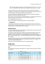
Calculating the maximum braking power for a custom duty cycle
These rules must be met during any braking cycle:
1.
Braking energy transferred during any ten minute period must be less than or equal to
the energy transferred during the reference braking cycle (1/9 min).
2.
The maximum braking power for a custom braking cycle (
P
br
) must not exceed the rated
maximum value
P
brmax
.
The rules as equations:
1.
n ×
P
br
×
t
br
≤
P
brmax
× 60 s =>
P
br
≤ (
P
brmax
× 60 s)/(n ×
t
br
)
2.
P
br
≤
P
brmax
Number of braking pulses during a 10-minute period
n
Maximum braking power (kW) for a custom braking cycle
P
br
Braking time (s)
t
br
Maximum braking power for a reference braking cycle (1 minute of braking, 9 minutes of rest)
P
brmax
Example 1
The duration of a braking cycle is 30 minutes. The braking time is 15 minutes.
Result:
If the braking time exceeds 10 minutes, the braking is considered continuous. The
allowed continuous braking power is 10% of maximum braking power (
P
brmax
).
Example 2
The duration of a braking cycle (
T
) is three minutes. The braking time (
t
br
) is 40 seconds.
1.
n ×
P
br
×
t
br
≤
P
brmax
× 60 s =>
P
br
≤ (
P
brmax
× 60 s) / (4 × 40 s) = 0.375
× P
brmax
2.
P
br
≤
P
brmax
<=> 0.375
× P
brmax
≤
P
brmax
OK
Result:
The maximum braking power for the custom braking cycle is 37% of the rated value
given for the reference cycle.
268 Resistor braking
Summary of Contents for ACS880-07
Page 1: ...ABB industrial drives Hardware manual ACS880 07 drives 560 to 2800 kW ...
Page 2: ......
Page 4: ......
Page 22: ...22 ...
Page 28: ...28 ...
Page 94: ...94 ...
Page 112: ...Electrical installation 109 5 6 4 3 112 Electrical installation ...
Page 113: ...110 Electrical installation 7 8 8 Electrical installation 113 ...
Page 114: ...Electrical installation 111 9 10 114 Electrical installation ...
Page 116: ...Electrical installation 113 4 5 3 6 7 116 Electrical installation ...
Page 118: ...2 11 b PE 10 7 5 6 8 a 360 grounding detail 118 Electrical installation ...
Page 128: ...128 ...
Page 146: ...146 ...
Page 148: ...148 ...
Page 159: ...12 Install and tighten the two M4 12 T20 screws 10 11 12 Maintenance 159 ...
Page 162: ...6 6a 6a 6b 7a 7b 7 8 8a 8b 162 Maintenance ...
Page 166: ...166 Maintenance 6 6 7 8 7 166 Maintenance ...
Page 173: ...6 Reinstall the cover removed earlier and close the cubicle door 4 4 D7T D8T Maintenance 173 ...
Page 213: ... Dimension drawing examples Frame 2 D7T 2 R8i 12 pulse A004 Dimensions 213 ...
Page 214: ...Frame 1 D8T 2 R8i IP22 214 Dimensions ...
Page 215: ...Frame 1 D8T 2 R8i IP54 B055 Dimensions 215 ...
Page 216: ...Frame 1 D8T 2 R8i with common motor terminal cubicle H359 1 2 216 Dimensions ...
Page 217: ...Frame 1 D8T 2 R8i with common motor terminal cubicle H359 2 2 Dimensions 217 ...
Page 218: ...Frame 1 D8T 2 R8i with brake choppers and resistors D150 D151 1 2 218 Dimensions ...
Page 219: ...Frame 1 D8T 2 R8i with brake choppers and resistors D150 D151 2 2 Dimensions 219 ...
Page 220: ...Frame 1 D8T 2 R8i with sine output filter E206 1 2 220 Dimensions ...
Page 221: ...Frame 1 D8T 2 R8i with sine output filter E206 2 2 Dimensions 221 ...
Page 222: ...Frame 2 D8T 2 R8i 12 pulse A004 with grounding switch F259 222 Dimensions ...
Page 223: ...Frame 2 D8T 3 R8i 1 2 Dimensions 223 ...
Page 224: ...Frame 2 D8T 3 R8i 2 2 224 Dimensions ...
Page 225: ...Frame 2 D8T 3 R8i with common motor terminal cubicle H359 1 2 Dimensions 225 ...
Page 226: ...Frame 2 D8T 3 R8i with common motor terminal cubicle H359 2 2 226 Dimensions ...
Page 227: ...Frame 2 D8T 3 R8i with top entry top exit H351 H353 1 2 Dimensions 227 ...
Page 228: ...Frame 2 D8T 3 R8i with top entry top exit 2 2 228 Dimensions ...
Page 229: ...Frame 3 D8T 4 R8i 1 2 Dimensions 229 ...
Page 230: ...Frame 3 D8T 4 R8i 2 2 230 Dimensions ...
Page 231: ...Frame 3 D8T 4 R8i with common motor terminal cubicle H359 1 2 Dimensions 231 ...
Page 232: ...Frame 3 D8T 4 R8i with common motor terminal cubicle H359 2 2 232 Dimensions ...
Page 233: ...Frame 3 D8T 4 R8i with top entry top exit H351 H353 1 2 Dimensions 233 ...
Page 234: ...Frame 3 D8T 4 R8i with top entry top exit H351 H353 2 2 234 Dimensions ...
Page 235: ...Frame 4 D8T 5 R8i 6 pulse with top entry exit UL Listed C129 1 2 Dimensions 235 ...
Page 236: ...Frame 4 D8T 5 R8i 6 pulse with top entry exit UL Listed C129 2 2 236 Dimensions ...
Page 237: ... Dimensions of empty cubicles options C199 C200 C201 IP22 IP42 Dimensions 237 ...
Page 238: ...IP54 238 Dimensions ...
Page 243: ... 1000 mm UL CSA top cable entry Dimensions 243 ...
Page 244: ... 1000 mm UL CSA bottom cable entry 244 Dimensions ...
Page 264: ...264 ...
Page 272: ... 272 ...


