


US
2)
IEC
1)
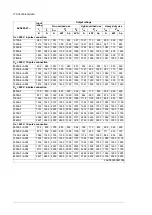
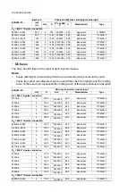
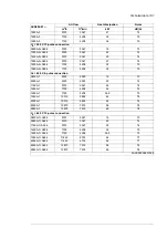
ACS880-07-…
Cu cable size
Cu cable size
Al cable size
AWG/kcmil
mm
2
mm
2
10 × 400
8 × (3 × 240 × 120)
12 × (3 × 185 + 57 Cu)
2300A-7+A004
11 × 400
15 × (3 × 120 × 70)
15 × (3 × 150 + 41 Cu)
2600A-7
2600A-7+A004
11 × 500
15 × (3 × 120 × 70)
15 × (3 × 185 + 57 Cu)
2860A-7
2860A-7+A004
+A004 = 12-pulse supply connection
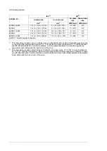
1)
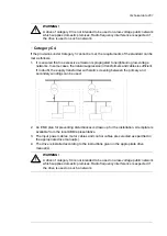
The cable sizing is based on max. 9 cables laid on a cable ladder side by side, three ladder type trays one
on top of the other, ambient temperature 30 °C, PVC insulation, surface temperature 70 °C (IEC/EN 60204-1
and IEC 60364-5-52/2001). For other conditions, size the cables according to local safety regulations,
appropriate input voltage and the load current of the drive.
2)
The cable sizing is based on NEC Table 310-15(B)(16) for copper wires, 75 °C (167 °F) wire insulation at
40 °C (104 °F) ambient temperature. Not more than three current-carrying conductors in raceway or cable
or earth (directly buried). For other conditions, size the cables according to local safety regulations, appropriate
input voltage and the load current of the drive.
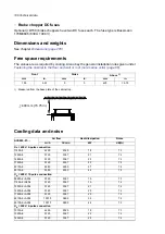
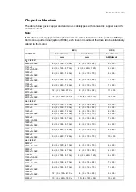
Terminal and lead-through data for the power cables
The locations and sizes of lead-throughs are shown by the dimension drawings delivered
with the drive, and the dimension drawing examples in this manual.
The location and size of power cable terminals are shown in the dimension drawing examples
in this manual.
Terminal data for the supply and inverter control units
See chapter
Control units of the drive (page 129)
.
Electrical power network specification
400 V units: 380…415 V AC 3-phase ± 10%. This is indicated in the type designation
label as typical input voltage level (3~ 400 V AC).
Voltage (
U
1
)
500 V units: 380…500 V AC 3-phase ± 10%. This is indicated in the type designation
label as typical input voltage levels (3~ 400/480/500 V AC).
690 V units: 525…690 V AC 3-phase ± 10% (525…600 V AC ± 10% in corner-
grounded TN systems). This is indicated in the type designation label as typical
input voltage levels (3~ 525/600/690 V AC).
TN (grounded) and IT (ungrounded) systems
Network type
50/60 Hz, variation ± 5% of nominal frequency
Frequency
Max. ± 3% of nominal phase-to-phase input voltage
Imbalance
ACS880-07-2610A-3, ACS880-07-2300A-7 and ACS880-07-2860A-7 without
grounding/earthing switch (ie. without F259):
Short-circuit withstand
strength (IEC/EN 61439-1)
Rated peak withstand current (
I
pk
): 143 kA
Rated short-time withstand current (
I
cw
): 65 kA/1 s
All other configurations:
Rated peak withstand current (
I
pk
): 105 kA
Rated short-time withstand current (
I
cw
): 50 kA/1 s
The drive is suitable for use on a circuit capable of delivering not more than 100,000
rms symmetrical amperes at 600 V maximum when the input cable is protected
with class T fuses.
Short-circuit current protec-
tion (UL 08A, CSA C22.2
No. 14-13)
0.98 (at nominal load)
Fundamental power factor
(cos phi
1
)
192 Technical data
Summary of Contents for ACS880-07
Page 1: ...ABB industrial drives Hardware manual ACS880 07 drives 560 to 2800 kW ...
Page 2: ......
Page 4: ......
Page 22: ...22 ...
Page 28: ...28 ...
Page 94: ...94 ...
Page 112: ...Electrical installation 109 5 6 4 3 112 Electrical installation ...
Page 113: ...110 Electrical installation 7 8 8 Electrical installation 113 ...
Page 114: ...Electrical installation 111 9 10 114 Electrical installation ...
Page 116: ...Electrical installation 113 4 5 3 6 7 116 Electrical installation ...
Page 118: ...2 11 b PE 10 7 5 6 8 a 360 grounding detail 118 Electrical installation ...
Page 128: ...128 ...
Page 146: ...146 ...
Page 148: ...148 ...
Page 159: ...12 Install and tighten the two M4 12 T20 screws 10 11 12 Maintenance 159 ...
Page 162: ...6 6a 6a 6b 7a 7b 7 8 8a 8b 162 Maintenance ...
Page 166: ...166 Maintenance 6 6 7 8 7 166 Maintenance ...
Page 173: ...6 Reinstall the cover removed earlier and close the cubicle door 4 4 D7T D8T Maintenance 173 ...
Page 213: ... Dimension drawing examples Frame 2 D7T 2 R8i 12 pulse A004 Dimensions 213 ...
Page 214: ...Frame 1 D8T 2 R8i IP22 214 Dimensions ...
Page 215: ...Frame 1 D8T 2 R8i IP54 B055 Dimensions 215 ...
Page 216: ...Frame 1 D8T 2 R8i with common motor terminal cubicle H359 1 2 216 Dimensions ...
Page 217: ...Frame 1 D8T 2 R8i with common motor terminal cubicle H359 2 2 Dimensions 217 ...
Page 218: ...Frame 1 D8T 2 R8i with brake choppers and resistors D150 D151 1 2 218 Dimensions ...
Page 219: ...Frame 1 D8T 2 R8i with brake choppers and resistors D150 D151 2 2 Dimensions 219 ...
Page 220: ...Frame 1 D8T 2 R8i with sine output filter E206 1 2 220 Dimensions ...
Page 221: ...Frame 1 D8T 2 R8i with sine output filter E206 2 2 Dimensions 221 ...
Page 222: ...Frame 2 D8T 2 R8i 12 pulse A004 with grounding switch F259 222 Dimensions ...
Page 223: ...Frame 2 D8T 3 R8i 1 2 Dimensions 223 ...
Page 224: ...Frame 2 D8T 3 R8i 2 2 224 Dimensions ...
Page 225: ...Frame 2 D8T 3 R8i with common motor terminal cubicle H359 1 2 Dimensions 225 ...
Page 226: ...Frame 2 D8T 3 R8i with common motor terminal cubicle H359 2 2 226 Dimensions ...
Page 227: ...Frame 2 D8T 3 R8i with top entry top exit H351 H353 1 2 Dimensions 227 ...
Page 228: ...Frame 2 D8T 3 R8i with top entry top exit 2 2 228 Dimensions ...
Page 229: ...Frame 3 D8T 4 R8i 1 2 Dimensions 229 ...
Page 230: ...Frame 3 D8T 4 R8i 2 2 230 Dimensions ...
Page 231: ...Frame 3 D8T 4 R8i with common motor terminal cubicle H359 1 2 Dimensions 231 ...
Page 232: ...Frame 3 D8T 4 R8i with common motor terminal cubicle H359 2 2 232 Dimensions ...
Page 233: ...Frame 3 D8T 4 R8i with top entry top exit H351 H353 1 2 Dimensions 233 ...
Page 234: ...Frame 3 D8T 4 R8i with top entry top exit H351 H353 2 2 234 Dimensions ...
Page 235: ...Frame 4 D8T 5 R8i 6 pulse with top entry exit UL Listed C129 1 2 Dimensions 235 ...
Page 236: ...Frame 4 D8T 5 R8i 6 pulse with top entry exit UL Listed C129 2 2 236 Dimensions ...
Page 237: ... Dimensions of empty cubicles options C199 C200 C201 IP22 IP42 Dimensions 237 ...
Page 238: ...IP54 238 Dimensions ...
Page 243: ... 1000 mm UL CSA top cable entry Dimensions 243 ...
Page 244: ... 1000 mm UL CSA bottom cable entry 244 Dimensions ...
Page 264: ...264 ...
Page 272: ... 272 ...


