


Electrical installation 85
Connection procedure for frames R1 to R3
1. Undo the mounting screws at the sides of the front cover.
2. Remove the cover by sliding it forward.
3. Attach the residual voltage warning sticker in the local language to the control
panel mounting platform.
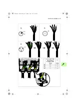
4. Remove the rubber grommets from the lead-through plate for the cables to be
connected.
5. IP21 units: Fasten the cable connectors (included in the delivery in a plastic bag)
to the cable lead-through plate holes.
6. Prepare the ends of the input power (a) and motor cables (b) as illustrated in the
figure.
Note
: Bare shield will be grounded 360 degrees.
7. IP21 units: Ground the shields 360 degrees in the connectors by tightening the
connector onto the stripped part of the cable. IP55 units: Tighten the clamps onto
the stripped part of the cables.
8. Connect the twisted shields of the power cables to the grounding terminals.
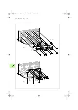
9. Connect the additional PE conductor (if used, see page
) of the input cable to
the grounding terminal.
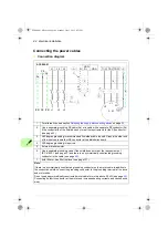
10. Connect the phase conductors of the input cable to the L1, L2 and L3 terminals
and the phase conductors of the motor cable to the T1/U, T2/V and T3/W
terminals. Connect the brake resistor conductors (if present) to the R+ and R-
terminals. Tighten the screws to the torque given in the figure below.
11. Install the control cable grounding shelf in the cable entry box.
12. Secure the cables outside the unit mechanically.
Note
: The drawings below show an IP21 unit. The IP55 unit looks slightly different.
For US cable conduit installation, see the quick installation guide.
ACS880-01 HW.book Page 85 Monday, July 1, 2013 4:51 PM
Summary of Contents for ACS880-01 Series
Page 4: ...ACS880 01 HW book Page 4 Monday July 1 2013 4 51 PM...
Page 12: ...12 ACS880 01 HW book Page 12 Monday July 1 2013 4 51 PM...
Page 20: ...20 Safety instructions ACS880 01 HW book Page 20 Monday July 1 2013 4 51 PM...
Page 26: ...26 Introduction to the manual ACS880 01 HW book Page 26 Monday July 1 2013 4 51 PM...
Page 80: ...80 Planning the electrical installation ACS880 01 HW book Page 80 Monday July 1 2013 4 51 PM...
Page 96: ...96 Electrical installation 8b R8 R9 ACS880 01 HW book Page 96 Monday July 1 2013 4 51 PM...
Page 98: ...98 Electrical installation 16 13 R8 R9 ACS880 01 HW book Page 98 Monday July 1 2013 4 51 PM...
Page 118: ...118 Start up ACS880 01 HW book Page 118 Monday July 1 2013 4 51 PM...
Page 120: ...120 Fault tracing ACS880 01 HW book Page 120 Monday July 1 2013 4 51 PM...
Page 131: ...Maintenance 131 3 4 5 3 ACS880 01 HW book Page 131 Monday July 1 2013 4 51 PM...
Page 172: ...172 Technical data ACS880 01 HW book Page 172 Monday July 1 2013 4 51 PM...
Page 196: ...196 Dimension drawings ACS880 01 HW book Page 196 Monday July 1 2013 4 51 PM...
Page 209: ...Safe Torque off function 209 Certificate ACS880 01 HW book Page 209 Monday July 1 2013 4 51 PM...
Page 210: ...210 Safe Torque off function ACS880 01 HW book Page 210 Monday July 1 2013 4 51 PM...
Page 220: ...220 Resistor braking ACS880 01 HW book Page 220 Monday July 1 2013 4 51 PM...


