


56 Guidelines for planning the electrical installation
Selecting the control cables
Shielding
All control cables must be shielded.
Use a double-shielded twisted pair cable for analog signals. ABB recommends this type of
cable for the pulse encoder signals also. Employ one individually shielded pair for each
signal. Do not use common return for different analog signals.
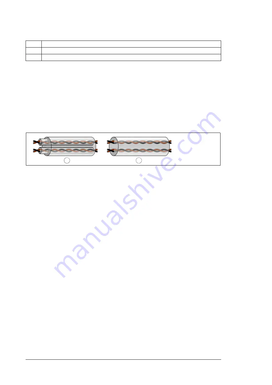
A double-shielded cable (figure a below) is the best alternative for low-voltage digital
signals but single-shielded (b) twisted pair cable is also acceptable.
Signals in separate cables
Run analog and digital signals in separate, shielded cables. Never mix 24 V DC and
115/230 V AC signals in the same cable.
Signals allowed to be run in the same cable
Relay-controlled signals, the voltage of which does not exceed 48 V, can be run in the
same cables as digital input signals. The relay-controlled signals should be run as twisted
pairs.
Relay cable type
The cable type with braided metallic screen (for example ÖLFLEX by LAPPKABEL,
Germany) has been tested and approved by ABB.
Control panel cable length and type
In remote use, the cable that connects the control panel to the drive must not be longer
than three meters (10 ft). Cable type: shielded CAT 5e or better Ethernet patch cable with
RJ-45 ends.
Routing the cables
Route the motor cable away from other cable routes. Motor cables of several drives can be
run in parallel installed next to each other. Install the motor cables, input power cables and
control cables on separate trays. Avoid long parallel runs of motor cables with other cables
in order to decrease electromagnetic interference caused by the rapid changes in the drive
output voltage.
Where control cables must cross power cables, arrange them at an angle as near to 90
degrees as possible. Do not run extra cables through the drive.
3
Copper wire screen
4
Inner insulation
5
Cable core
a
b
Summary of Contents for ACS580-07-0495A-4
Page 1: ...ABB general purpose drives Hardware manual ACS580 07 drives 250 to 500 kW ...
Page 4: ......
Page 8: ...4 Update notice ...
Page 16: ...12 ...
Page 24: ...20 Safety instructions ...
Page 42: ...38 Operation principle and hardware description ...
Page 74: ...70 Electrical installation PE PE 8 PE 13 11 7 8 12 13 ...
Page 82: ...78 Electrical installation ...
Page 102: ...98 Fault tracing ...
Page 114: ...110 Maintenance R10 and R11 4 5 2 7 6 3 8 ...
Page 115: ...Maintenance 111 R10 and R11 9 10 ...
Page 116: ...112 Maintenance R10 and R11 11 ...
Page 117: ...Maintenance 113 R10 and R11 12b 12a ...
Page 118: ...114 Maintenance R10 and R11 R10 and R11 17 14 13 R11 15 16 ...
Page 134: ...130 Technical data ...
Page 137: ...Dimension drawings 133 13 Dimension drawings Example dimension drawings are shown below ...
Page 138: ...134 Dimension drawings Frames R10 and R11 IP42 ...
Page 139: ...Dimension drawings 135 Frames R10 and R11 IP54 option B055 ...
Page 140: ...136 Dimension drawings ...
Page 152: ...148 Safe torque off function ...
Page 174: ...Contact us www abb com drives www abb com drivespartners 3AXD50000032622 Rev A EN 2016 03 16 ...


