Planning the electrical installation 67
temperature indication given by motor temperature sensors. The user can tune the
thermal model further by feeding in additional motor and load data.
The most common temperature sensors are:
• motor sizes IEC180…225: thermal switch, eg, Klixon
• motor sizes IEC200…250 and larger: PTC or Pt100.
For more information, see
ACS580 firmware manual
(3AXD50000016097 [English]).
Protecting the drive against ground faults
The drive is equipped with an internal ground fault protective function to protect the
unit against ground faults in the motor and motor cable. This is not a personnel safety
or a fire protection feature. The ground fault protective function can be reduced with a
parameter 31.20 Earth fault.
Residual current device compatibility
The drive is suitable to be used with residual current devices of Type B.
Note:
The EMC filter of the drive includes capacitors connected between the main
circuit and the frame. These capacitors and long motor cables increase the ground
leakage current and may cause fault current circuit breakers to function.
Implementing the Emergency stop function
For safety reasons, install the emergency stop devices at each operator control
station and at other operating stations where emergency stop may be needed.
Design the emergency stop according to relevant standards.
Note:
Pressing the stop key
on the control panel of the drive does not generate
an emergency stop of the motor or separate the drive from dangerous potential.
Implementing the Safe torque off function
See chapter
on page
Implementing the undervoltage control (power-loss ride-
through)
See
ACS580 firmware manual
(3AXD50000016097 [English]).
Using a safety switch between the drive and the motor
It is recommended to install a safety switch between the permanent magnet motor
and the drive output. This is needed to isolate the motor from the drive during
maintenance work on the drive.
Summary of Contents for ACS580-01 drives
Page 1: ...ABB general purpose drives Hardware manual ACS580 01 drives 0 75 to 250 kW...
Page 4: ......
Page 11: ...Table of contents 11 Document library on the Internet 225...
Page 12: ...12 Table of contents...
Page 72: ...72 Planning the electrical installation...
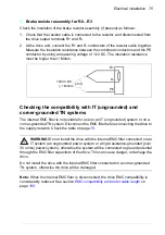
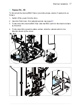
Page 79: ...Electrical installation 79 R6 R9 3 3 4...
Page 132: ...132 Maintenance and hardware diagnostics...
Page 168: ...168 Dimension drawings Frame R0 IP21 3AXD10000257110...
Page 169: ...Dimension drawings 169 Frame R0 IP55 3AXD10000341562...
Page 170: ...170 Dimension drawings Frame R1 IP21 3AXD10000257188...
Page 171: ...Dimension drawings 171 Frame R1 IP55 3AXD10000336766...
Page 172: ...172 Dimension drawings Frame R2 IP21 3AXD10000257203...
Page 173: ...Dimension drawings 173 Frame R2 IP55 3AXD10000341578...
Page 174: ...174 Dimension drawings Frame R3 IP21 3AXD10000257219...
Page 175: ...Dimension drawings 175 Frame R3 IP55 3AXD10000335424...
Page 176: ...176 Dimension drawings Frame R4 IP21 3AXD10000332430...
Page 177: ...Dimension drawings 177 Frame R4 IP55 3AXD10000427933...
Page 178: ...178 Dimension drawings Frame R5 IP21 3AXD10000412280...
Page 179: ...Dimension drawings 179 Frame R5 IP55 3AXD10000415964...
Page 180: ...180 Dimension drawings Frame R6 IP21 3AXD10000258705...
Page 181: ...Dimension drawings 181 Frame R6 IP55 3AXD10000330667...
Page 182: ...182 Dimension drawings Frame R7 IP21 3AXD10000258995...
Page 183: ...Dimension drawings 183 Frame R7 IP55 3AXD10000330932...
Page 184: ...184 Dimension drawings Frame R8 IP21 3AXD10000287670...
Page 185: ...Dimension drawings 185 Frame R8 IP55 3AXD10000332446...
Page 186: ...186 Dimension drawings Frame R9 IP21 3AXD10000287428...
Page 187: ...Dimension drawings 187 Frame R9 IP55 3AXD10000334310...
Page 188: ...188 Dimension drawings...
Page 196: ...196 Resistor braking...

