Mechanical installation 55
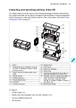
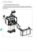
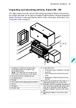
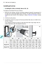
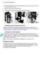
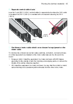
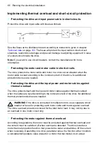
Installing the drive vertically, frames
R6…R9
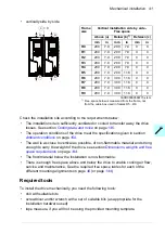
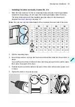
1. Mark the hole locations for the six mounting holes using the mounting template
included in the package. Do not leave the mounting template under the drive.
The drive dimensions and hole locations are also shown in the drawings in
chapter
on page
.
Note:
You can use only two bolts instead of four to attach the lower part of the drive.
2. Drill the mounting holes.
3. Insert fixing anchors or plugs into the holes and start the bolts into the anchors or
plugs.
Use a sufficient number of bolts and drive them long enough into the wall to make
them carry the weight of the drive.
4. Position the drive onto the bolts on the wall. Lift the drive with another person as it
is heavy.
5. Tighten the bolts in the wall securely.
c
a
d
e
b
R6
R7
R8
R9
mm
in
mm
in
mm
in
mm
in
a
571
22.5
623
24.5
701
27.6
718
28.3
b
531
20.9
583
22.9
658
25.9
658
25.9
c
213
8.4
245
9.7
263
10.4
345
13.6
d
300
11.8
300
11.8
300
11.8
300
11.8
e
200
7.9
200
7.9
200
7.9
200
7.9
IP21
kg
lb
kg
lb
kg
lb
kg
lb
45
99
55
121
70
154
98
216
IP55
kg
lb
kg
lb
kg
lb
kg
lb
46
101.4
56
123.5
74
163.2 102 224.9
1
× 4
3
× 2
× 2
4
2
5
M8
Summary of Contents for ACS580-01 drives
Page 1: ...ABB general purpose drives Hardware manual ACS580 01 drives 0 75 to 250 kW...
Page 4: ......
Page 11: ...Table of contents 11 Document library on the Internet 225...
Page 12: ...12 Table of contents...
Page 72: ...72 Planning the electrical installation...
Page 79: ...Electrical installation 79 R6 R9 3 3 4...
Page 132: ...132 Maintenance and hardware diagnostics...
Page 168: ...168 Dimension drawings Frame R0 IP21 3AXD10000257110...
Page 169: ...Dimension drawings 169 Frame R0 IP55 3AXD10000341562...
Page 170: ...170 Dimension drawings Frame R1 IP21 3AXD10000257188...
Page 171: ...Dimension drawings 171 Frame R1 IP55 3AXD10000336766...
Page 172: ...172 Dimension drawings Frame R2 IP21 3AXD10000257203...
Page 173: ...Dimension drawings 173 Frame R2 IP55 3AXD10000341578...
Page 174: ...174 Dimension drawings Frame R3 IP21 3AXD10000257219...
Page 175: ...Dimension drawings 175 Frame R3 IP55 3AXD10000335424...
Page 176: ...176 Dimension drawings Frame R4 IP21 3AXD10000332430...
Page 177: ...Dimension drawings 177 Frame R4 IP55 3AXD10000427933...
Page 178: ...178 Dimension drawings Frame R5 IP21 3AXD10000412280...
Page 179: ...Dimension drawings 179 Frame R5 IP55 3AXD10000415964...
Page 180: ...180 Dimension drawings Frame R6 IP21 3AXD10000258705...
Page 181: ...Dimension drawings 181 Frame R6 IP55 3AXD10000330667...
Page 182: ...182 Dimension drawings Frame R7 IP21 3AXD10000258995...
Page 183: ...Dimension drawings 183 Frame R7 IP55 3AXD10000330932...
Page 184: ...184 Dimension drawings Frame R8 IP21 3AXD10000287670...
Page 185: ...Dimension drawings 185 Frame R8 IP55 3AXD10000332446...
Page 186: ...186 Dimension drawings Frame R9 IP21 3AXD10000287428...
Page 187: ...Dimension drawings 187 Frame R9 IP55 3AXD10000334310...
Page 188: ...188 Dimension drawings...
Page 196: ...196 Resistor braking...

