ACS550 User’s Manual
43
Control panels
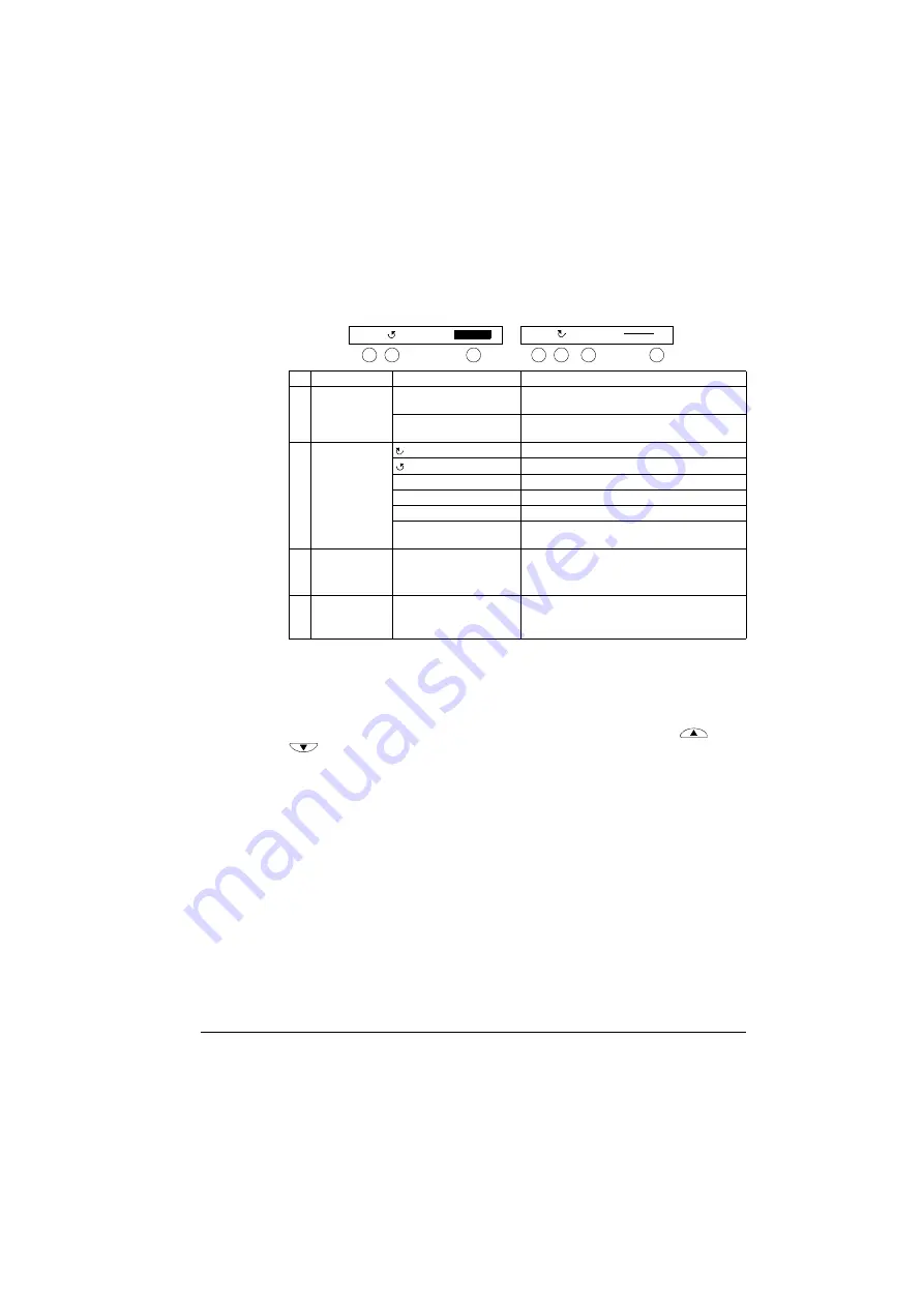
Status line
The top line of the LCD display shows the basic status information of the drive.
Operation
You operate the control panel with menus and keys. The keys include two context-
sensitive soft keys, whose current function is indicated by the text shown in the
display above each key.
You select an option, e.g. operation mode or parameter, by scrolling the
and
arrow keys
until the option is highlighted (in reverse video) and then pressing
the relevant soft key. With the right soft key you usually enter a mode, accept an
option or save the changes. The left soft key is used to cancel the made changes
and return to the previous operation level.
The Assistant Control Panel has nine panel modes: Output, Parameters, Assistants,
Changed Parameters, Fault Logger, Clock Set, Parameter Backup, I/O Settings and
Fault. The operation in the first eight modes is described in this chapter. When a fault
or alarm occurs, the panel goes automatically to the Fault mode showing the fault or
alarm. You can reset it in the Output or Fault mode (see chapter
No. Field
Alternatives
Significance
1 Control location
LOC
Drive control is local, that is, from the control
panel.
REM
Drive control is remote, such as the drive I/O or
fieldbus.
2 State
Forward shaft direction
Reverse shaft direction
Rotating arrow
Drive is running at setpoint.
Dotted rotating arrow
Drive is running but not at setpoint.
Stationary arrow
Drive is stopped.
Dotted stationary arrow
Start command is present, but the motor is not
running, e.g. because start enable is missing.
3 Panel operation
mode
• Name of the current mode
• Name of the list or menu shown
• Name of the operation state, e.g. PAR EDIT.
4 Reference value
or number of the
selected item
• Reference value in the Output mode
• Number of the highlighted item, e.g mode,
parameter group or fault.
49.1Hz
LOC
1
2
4
LOC
MAIN MENU
1
1
2
3
4
Summary of Contents for ACS550 Series
Page 1: ...ACS550 User s Manual ACS550 01 Drives 0 75 132 kW ACS550 U1 Drives 1 200 hp ...
Page 4: ......
Page 10: ...10 ACS550 User s Manual Table of contents ...
Page 84: ...84 ACS550 User s Manual Application macros ...
Page 188: ...188 ACS550 User s Manual Parameters ...
Page 242: ...242 ACS550 User s Manual Fieldbus adapter ...
Page 276: ...276 ACS550 User s Manual Technical data WARNING Do not use RFI EMC filters on IT systems ...


