


06 ELECTRICAL INSTALLATION
3BHS212794 E01 REV M
ACS6000
USER MANUAL
164/278
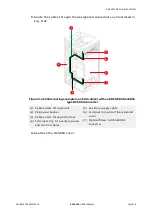
6.8.8
Routing Azipod® encoder cables
This section applies to Azipod® propulsion.
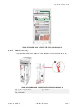
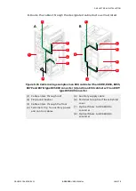
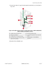
The number of the pulse encoders and receivers, and the location of the
receivers depend on the configuration of the drive. The receivers are
installed in one of the following units:
• CIU
• WCU
• COU
Note:
For project-specific details, see the “Converter hardware diagram”
in “Appendix D – Wiring diagrams”.
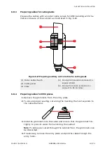
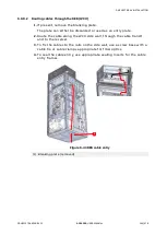
6.8.8.1
Handling and installation
The signals from the position encoders in the Azipod® to the receivers in
the drive are transmitted with fiber optics.
▲
NOTICE
Risk of equipment failure!
• If an optical fiber is damaged or improperly installed, data
transmission can be affected, and the equipment can fail. To
prevent such problems, follow the handling and
installation guidelines.
• To protect the optical fibers against damages, lay them in a steel or
plastic conduit, that is only used for the encoder cables. The
conduit starts at the drive and ends inside the EXU. At the drive, the
conduit enters through the entry plate with about 10 – 20 mm of
conduit extending from the entry plate.
• To protect the tip of the optical fiber against scratches, cover the
cable end with a cap before pulling the cable through the conduit.
• DO NOT exceed the specified maximum tensile load and the
minimum bend radius of the optical fiber.
• When using cable ties, be careful not to deform the optical fibers
and DO NOT use a cable tie gun.
• When connecting or unplugging an optical fiber, hold it at the
connector and not at the fiber.


