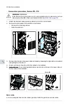


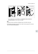


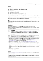

Control cable connection procedure R0…R8
WARNING!
Obey the instructions in chapter
. If you ignore them, injury or
death, or damage to the equipment can occur.
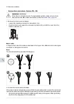
1.
Stop the drive and perform the steps in section
Electrical safety precautions (page 14)
before you start the work.
2.
Remove the front cover(s) if not already removed. See section
Connection procedure, frames R3...R4 (page 76)
or
the drive vertically, frames size R5…R8 (page 48)
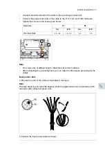
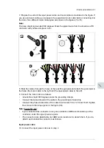
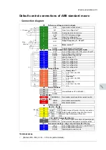
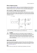
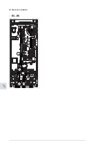
Analog signals
The figures for frames
,
and
show an example of connecting a cable. Make the connections according to the macro
in use.
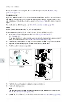
3.
Frames R4...R8: Cut an adequate hole into the rubber grommet and slide the grommet
onto the cable. Slide the cable through a hole in the lead-through plate and attach the
grommet to the hole.
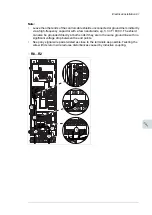
4.
Ground the outer shield of the cable 360 degrees under the grounding clamp. Keep the
cable unstripped as close to the terminals of the control board as possible.
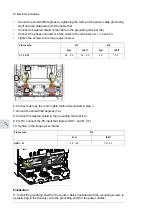
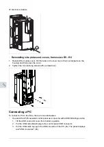
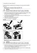
Frames R5…R8: Secure the cables mechanically at the clamps below the control board.
Ground also the pair-cable shields and grounding wire at the SCR terminal.
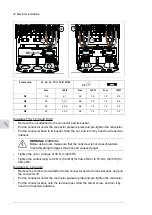
5.
Route the cable as shown in the figures
and
.
6.
Connect the conductors to the appropriate terminals of the control board and tighten to
0.5…0.6 N·m (0.4 lbf·ft).
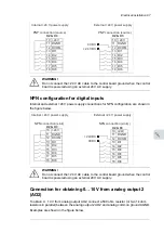
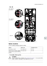
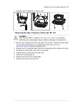
Digital signals
The figures for frames
,
and
show an example of connecting a cable. Make the connections according to the macro
in use.
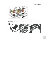
7.
Frames R4...R8: Cut an adequate hole into the rubber grommet and slide the grommet
onto the cable. Slide the cable through the hole in the lead-through plate and attach the
grommet to the hole.
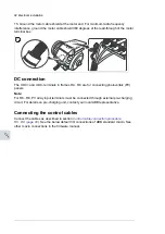
8.
Ground the outer shield of the cable 360 degrees under the grounding clamp. Keep the
cable unstripped as close to the terminals of the control board as possible.
Frames R5…R8: Secure the cables mechanically at the clamps below the control board.
If you use double-shielded cables, ground also the pair-cable shields and grounding
wire at the SCR terminal.
9.
Route the cable as shown in the figures
and
.
10. Connect the conductors to the appropriate terminals of the control board and tighten to
0.5…0.6 N·m (0.4 lbf·ft).
11. Tie all control cables to the provided cable tie mounts.
90 Electrical installation
Summary of Contents for ACQ80-04 Series
Page 1: ...ABB DRIVES FOR WATER ACQ80 04 drives 0 75 to 160 kW 1 0 to 215 hp Hardware manual...
Page 2: ......
Page 4: ......
Page 18: ...18...
Page 24: ...24...
Page 38: ...38...
Page 50: ...50...
Page 64: ...64...
Page 98: ...98...
Page 110: ...110...
Page 140: ...Frame R3 IP20 140 Dimension drawings...
Page 146: ...146...
Page 162: ...162...
Page 168: ......


