


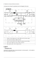


The figure below shows the simplified main circuit diagram of the drive.
L1
L2
L3
T1/U
T2/V
T3/W
1
2
3
Rectifier. Converts alternating current and voltage to direct current and voltage.
1
DC link. DC circuit between rectifier and inverter.
2
Inverter. Converts direct current and voltage to alternating current and voltage.
3
UDC-, UDC+ in frames R0…R2 and R-, UDC+ in frame R3
4
DC connection (UDC+, UDC-) in frames R4…R8.
5
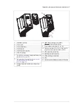
Layout
■
Frames R0...R2
The layout of a frame R0 drive is presented below. The frame sizes R1…R2 is similar to
R0 but have a different structure.
26 Operation principle and hardware description
Summary of Contents for ACQ80-04 Series
Page 1: ...ABB DRIVES FOR WATER ACQ80 04 drives 0 75 to 160 kW 1 0 to 215 hp Hardware manual...
Page 2: ......
Page 4: ......
Page 18: ...18...
Page 24: ...24...
Page 38: ...38...
Page 50: ...50...
Page 64: ...64...
Page 98: ...98...
Page 110: ...110...
Page 140: ...Frame R3 IP20 140 Dimension drawings...
Page 146: ...146...
Page 162: ...162...
Page 168: ......


