


■
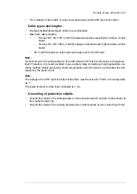
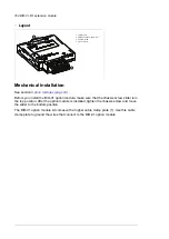
Layout
1
3
2
4
1. Locking tab
2. Fieldbus option module slot
3. Chassis screw
4. I/O connector
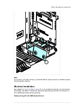
Mechanical installation
See section
.
Before you install the BIO-01 option module, make sure that the chassis screw slider is in
the top position. After the option module is installed, tighten the chassis screw and move
the slider to the bottom position.
The BIO-01 option module kit comes with a higher cable clamp plate (1). Use this cable
clamp plate to ground the wires that connect to the BIO-01 option module.
164 BIO-01 I/O extension module
Summary of Contents for ACQ80-04 Series
Page 1: ...ABB DRIVES FOR WATER ACQ80 04 drives 0 75 to 160 kW 1 0 to 215 hp Hardware manual...
Page 2: ......
Page 4: ......
Page 18: ...18...
Page 24: ...24...
Page 38: ...38...
Page 50: ...50...
Page 64: ...64...
Page 98: ...98...
Page 110: ...110...
Page 140: ...Frame R3 IP20 140 Dimension drawings...
Page 146: ...146...
Page 162: ...162...
Page 168: ......


