


Planning the layout
■
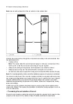
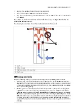
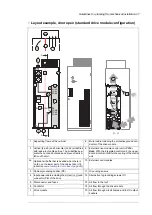
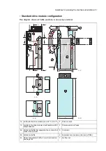
Layout example, door closed
This diagram shows a cabinet layout example with the input power cable entry from top and
the motor cable entry from bottom.
Air inlet for the drive module
1a
1a
4
3
2a
2b
5
6
7
1c
1b
2c
Air inlet for the other equipment. An extra fan is not
necessary if an extra air baffle is used on the cabinet
roof, see
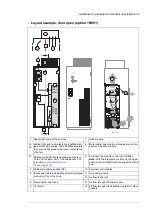
Layout example, door open (standard drive
module configuration) (page 47)
.
1b
Air inlet for circuit boards and DC and output busbars
1c
Air outlet with an extra exhaust fan for the drive
module
2a
Air outlet for the other equipment
2b
Air outlet for the drive module and other equipment
on the cabinet roof. An exhaust fan if needed. ABB
recommends this alternative instead of 2a.
2c
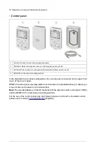
Drive control panel with DPMP-03 mounting platform.
The control panel is connected to the drive module
control unit inside the cabinet.
3
Contactor control switch and emergency stop switch
(connected to the contactor control circuit inside the
cabinet)
4
Operating handle of the disconnector
5
Rubber grommets for degree of protection
6
Roof air flow viewed from top
7
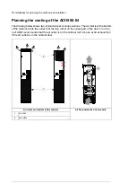
Note:
The sizes of the air inlet and outlet gratings are
critical for the cooling of the drive module. For losses and
cooling data requirements, see section
.
46 Guidelines for planning the mechanical installation
Summary of Contents for ACH580-04
Page 1: ... ABB DRIVES FOR HVAC ACH580 04 drive modules Hardware manual ...
Page 2: ......
Page 4: ......
Page 54: ...54 ...
Page 88: ...88 ...
Page 100: ...100 ...
Page 118: ...118 ...
Page 122: ...122 ...
Page 124: ...124 ...
Page 128: ...3 6 5 5 128 Maintenance ...
Page 134: ...134 ...
Page 156: ...R10 standard configuration 156 Dimension drawings ...
Page 157: ...R10 with E208 0H354 H356 H370 0H371 Dimension drawings 157 ...
Page 158: ...R10 with option B051 158 Dimension drawings ...
Page 159: ...R10 with option E208 H356 P906 192 Tools R10 3 1 Dimension drawings 159 ...
Page 160: ...R10 with option E208 0H371 H356 0H354 H370 P906 Tools 191 R10 2 1 160 Dimension drawings ...
Page 161: ...R10 with option B051 P906 190 Tools R10 1 1 Dimension drawings 161 ...
Page 162: ...R11 standard configuration 162 Dimension drawings ...
Page 163: ...R11 with option E208 0H371 H356 0H354 H370 Dimension drawings 163 ...
Page 164: ...R11 with option B051 164 Dimension drawings ...
Page 165: ...R11 with option E208 H356 P906 Dimension drawings 165 ...
Page 166: ...R11 with option E208 0H371 H356 0H354 H370 P906 166 Dimension drawings ...
Page 167: ...R11 with option B051 P906 Dimension drawings 167 ...
Page 186: ... Declaration of conformity 186 The Safe torque off function ...
Page 206: ...Dimension drawing 206 External control unit option P906 ...
Page 212: ...212 ...
Page 224: ...224 ...
Page 226: ...226 ...
Page 234: ...234 ...


