


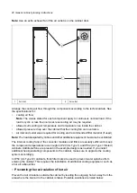


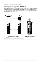


Note:
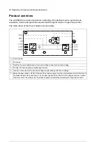
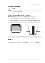
Use an extra exhaust fan if the air outlet is on the cabinet door.
Air outlet
2
Air inlet
1
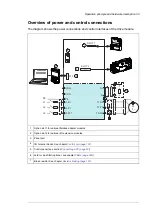
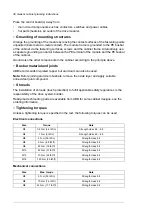
Arrange the cooling air flow through the components according to the technical data. See
the specifications for:
•
cooling air flow
Note:
The values stated for each component apply to continuous nominal load. If the
load is cyclic or less than nominal, less cooling air may be required.
•
allowed surrounding air temperature and temperature rise inside the cabinet
•
allowed pressure drop over the cabinet that the cooling fan can overcome
•
air inlet and outlet sizes required for cooling and recommended filter material (if used).
Note:
The heat dissipated by cables and other additional equipment must also be ventilated.
The internal cooling fans of the converter modules and filters are usually sufficient to keep
the component temperatures low enough in IP20 (UL Type 1) and IP42 (UL Type 1 filtered)
cabinets. Additional fans are present in the example designs as needed. If you install
additional heat-generating components to the cabinet, make sure to upgrade the cooling
system accordingly.
In IP54 (UL Type 12) cabinets, thick filter mats are used to prevent water splashes from
entering the cabinet. This requires the installation of additional cooling equipment, such as
a hot air exhaust fan.
■
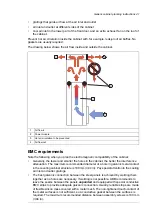
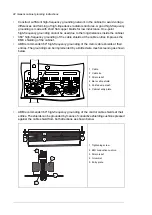
Preventing the recirculation of hot air
Prevent hot air circulation outside the cabinet by leading the outgoing hot air away from the
area where the inlet air to the cabinet is taken. Possible solutions are listed below:
40 Generic cabinet planning instructions
Summary of Contents for ACH580-04
Page 1: ... ABB DRIVES FOR HVAC ACH580 04 drive modules Hardware manual ...
Page 2: ......
Page 4: ......
Page 54: ...54 ...
Page 88: ...88 ...
Page 100: ...100 ...
Page 118: ...118 ...
Page 122: ...122 ...
Page 124: ...124 ...
Page 128: ...3 6 5 5 128 Maintenance ...
Page 134: ...134 ...
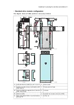
Page 156: ...R10 standard configuration 156 Dimension drawings ...
Page 157: ...R10 with E208 0H354 H356 H370 0H371 Dimension drawings 157 ...
Page 158: ...R10 with option B051 158 Dimension drawings ...
Page 159: ...R10 with option E208 H356 P906 192 Tools R10 3 1 Dimension drawings 159 ...
Page 160: ...R10 with option E208 0H371 H356 0H354 H370 P906 Tools 191 R10 2 1 160 Dimension drawings ...
Page 161: ...R10 with option B051 P906 190 Tools R10 1 1 Dimension drawings 161 ...
Page 162: ...R11 standard configuration 162 Dimension drawings ...
Page 163: ...R11 with option E208 0H371 H356 0H354 H370 Dimension drawings 163 ...
Page 164: ...R11 with option B051 164 Dimension drawings ...
Page 165: ...R11 with option E208 H356 P906 Dimension drawings 165 ...
Page 166: ...R11 with option E208 0H371 H356 0H354 H370 P906 166 Dimension drawings ...
Page 167: ...R11 with option B051 P906 Dimension drawings 167 ...
Page 186: ... Declaration of conformity 186 The Safe torque off function ...
Page 206: ...Dimension drawing 206 External control unit option P906 ...
Page 212: ...212 ...
Page 224: ...224 ...
Page 226: ...226 ...
Page 234: ...234 ...


