


ACH550-UH User’s Manual
1-155
Parameters
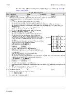
4010
SET POINT SEL
0…2, 8…17, 19…20
1
0 (
KEYPAD
)
Defines the reference signal source for the PID controller.
• Parameter has no significance when the PID regulator is by-passed (see 8121
REG
BYPASS
CTRL
).
0 =
KEYPAD
– Control panel provides reference.
1 =
AI
1 – Analog input 1 provides reference.
2 =
AI
2 – Analog input 2 provides reference.
8 =
COMM
– Fieldbus provides reference.
9 =
COMM
+
AI
1 – Defines a fieldbus and analog input 1 (
AI
1) combination as the reference source. See Analog input
reference correction below.
10 =
COMM
*
AI
1 – Defines a fieldbus and analog input 1 (
AI
1) combination as the reference source. See Analog input
reference correction below.
11 =
DI
3
U
,4
D
(
RNC
) – Digital inputs, acting as a motor potentiometer control, provide reference.
•
DI
3 increases the speed (the U stands for “up”)
•
DI
4 decreases the reference (the D stands for “down”).
• Parameter 2205
ACCELER
TIME
2 controls the reference signal’s rate of change.
• R = Stop command resets the reference to zero.
• NC = Reference value is not copied.
12 =
DI
3
U
,4
D
(
NC
) – Same as
DI
3
U
,4
D
(
RNC
) above, except:
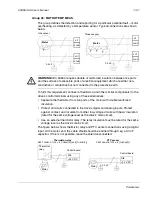
• Stop command does not reset reference to zero. At restart the motor ramps up, at the selected acceleration rate,
to the stored reference.
13 =
DI
5
U
,6
D
(
NC
) – Same as
DI
3
U
,4
D
(
NC
) above, except:
• Uses digital inputs
DI
5 and
DI
6.
14 =
AI
1+
AI
2 – Defines an analog input 1 (
AI
1) and analog input 2 (
AI
2) combination as the reference source. See
Analog input reference correction below.
15 =
AI
1*
AI
2 – Defines an analog input 1 (
AI
1) and analog input 2 (
AI
2) combination as the reference source. See
Analog input reference correction below.
16 =
AI
1-
AI
2 – Defines an analog input 1 (
AI
1) and analog input 2 (
AI
2) combination as the reference source. See
Analog input reference correction below.
17 =
AI
1/
AI
2 – Defines an analog input 1 (
AI
1) and analog input 2 (
AI
2) combination as the reference source. See
Analog input reference correction below.
19 =
INTERNAL
– A constant value set using parameter 4011 provides reference.
20 =
PID
2
OUT
– Defines PID controller 2 output (parameter 0127
PID
2
OUTPUT
) as the reference source.
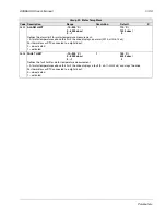
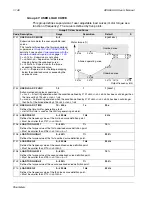
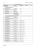
Analog input reference correction
Parameter values 9, 10 and 14…17 use the formula in the following table.
Where:
• C = Main reference value
( =
COMM
for values 9, 10 and
=
AI
1 for values 14…17)
• B = Correcting reference
( =
AI
1 for values 9, 10 and
=
AI
2 for values 14…17).
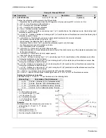
Example:
The figure shows the reference source curves for
value settings 9, 10 and 14…17, where:
• C = 25%.
• P 4012
SETPOINT
MIN
= 0.
• P 4013
SETPOINT
MAX
= 0.
• B varies along the horizontal axis.
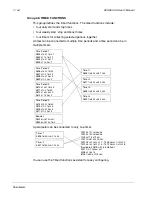
Group 40: Process PID Set 1
Code Description Range
Resolution
Default
S
Value setting
Calculation of the AI reference
C + B
C value + (B value - 50% of reference value)
C * B
C value · (B value / 50% of reference value)
C - B
(C value + 50% of reference value) - B value
C / B
(C value · 50% of reference value) / B value
120
100
80
60
40
20
0
0
100%
9, 14 (+)
16 (-)
10, 15 (*)
17 (/)
B
Summary of Contents for ACH550-UH HVAC
Page 2: ......
Page 8: ...1 8 ACH550 UH User s Manual Table of contents ...
Page 32: ...1 32 ACH550 UH User s Manual Installation ...
Page 66: ...1 66 ACH550 UH User s Manual Application macros ...
Page 186: ...1 186 ACH550 UH User s Manual Parameters ...
Page 333: ...ACH550 UH User s Manual 1 333 Technical data ...


