


3
)
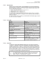
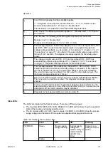
Fixed Mapping means each module has its own Modbus registers for
data transfer independent of the I/O bus constellation description. For
details see.
Dynamic mapping means the structure of the IO Date is dependent on
the I/O bus constellation. Each I/O bus expansion module starts directly
after the module before on the next Word adress.
4
)
If none of the parameters is set all masters / clients in the network have
read and write rights on the CI52x-MODTCP device and its connected
expansion modules.
If at least one parameter is set only the configured masters / clients have
write rights on the CI52x-MODTCP device, all other masters / clients still
have read access to the CI52x-MODTCP device.
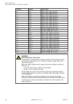
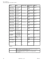
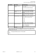
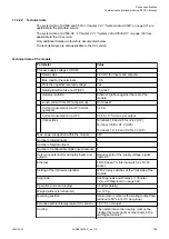
Table 163: Table Error LED / Failsafe function
Setting
Description
On
Error LED (S-ERR) lights up at errors of all
error classes, Failsafe-mode off
Off by E4
Error LED (S-ERR) lights up at errors of error
classes E1, E2 and E3, Failsafe-mode off
Off by E3
Error LED (S-ERR) lights up at errors of error
classes E1 and E2, Failsafe-mode off
On + Failsafe
Error LED (S-ERR) lights up at errors of all
error classes, Failsafe-mode on *)
Off by E4 + Failsafe
Error LED (S-ERR) lights up at errors of error
classes E1, E2 and E3, Failsafe-mode on *)
Off by E3 + Failsafe
Error LED (S-ERR) lights up at errors of error
classes E1 and E2, Failsafe-mode on *)
*) The parameter Behaviour DO at comm. error is only analyzed if the Failsafe-mode is ON.
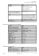
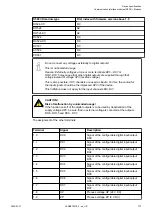
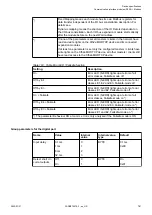
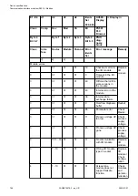
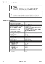
Group parameters for the digital part
Name
Value
Internal
value
Internal value,
type
Default
Input delay
0.1 ms
1 ms
8 ms
32 ms
0
1
2
3
BYTE
0.1 ms
0x00
Detect short cir-
cuit at outputs
Off
On
0
1
BYTE
On
0x01
Device specifications
Communication interface modules (S500) > Modbus
2022/01/31
3ADR010278, 3, en_US
781