


Mounting AC 800M Units onto DIN-Rail
Section 2 Installation
50
3BSE 027 941 R301
Mounting Procedure for PM8xx and CI8xx Units, Complete with Baseplates
Before mounting any processor unit or communication interface onto the DIN-rail,
read carefully the installation instructions provided with the equipment. Since the
electronic unit and baseplate are supplied as a single unit, there is no requirement to
separate them during the mounting procedure.
Mounting the units onto the DIN-rail only requires a blade screwdriver that fits
securely into the baseplate locking screw (1 mm slot). For further details on
mounting procedure, see
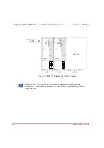
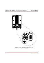
Use the procedure below to mount the baseplates, complete with units:
1.
Rotate the locking device to the OPEN position (1), hook the upper lip at the
rear of the unit baseplate securely over the upper edge of the DIN-rail and
gently snap the baseplate fully into the mounting position.
2.
Rotate the locking device to the SLIDE position (2), gently slide the unit along
the DIN-rail to the desired mounting position and using the connector plugs
and sockets gently attach it to the adjacent unit baseplate.
3.
When interconnection is complete, rotate the locking device clockwise to
the LOCKED position (3). The baseplate is now fully locked into position and
has a good ground connection to the DIN-rail.
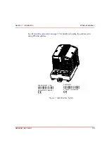
For further visual information on mounting AC 800M Controller units, see
To prevent damage to the pins, be sure the baseplate plugs and sockets are fully
aligned as the units interconnect.Under no circumstances use excessive force!
It is essential that the locking device be placed in the LOCKED position to
avoid possible problems caused by vibration and/or intermittent grounding.
Summary of Contents for AC 800M
Page 1: ...ControlIT AC 800M Version 2 1 Controller Hardware Hardware and Operation...
Page 2: ......
Page 3: ...Controller Hardware Hardware and Operation ControlIT AC 800M Version 2 1...
Page 10: ...7DEOH RI RQWHQWV 10 3BSE 027 941 R301...
Page 20: ...Related Documentation About This Book 20 3BSE 027 941 R301...
Page 26: ...Operating Environment Safety Summary 26 3BSE 027 941 R301...
Page 42: ...Product Release History Section 1 Introduction 42 3BSE 027 941 R301...
Page 108: ...Powering from an External 24 V DC Source Section 3 Configuration 108 3BSE 027 941 R301...
Page 118: ...Verification of Redundant CPU Section 4 Operation 118 3BSE 027 941 R301...
Page 212: ...Low Voltage Directive LVD Appendix D Directive Considerations 212 3BSE 027 941 R301...
Page 214: ...Hazardous Location Approval Appendix E Standards 214 3BSE 027 941 R301...
Page 228: ...QGH 228 3BSE 027 941 R301...
Page 229: ......


