


62
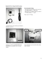
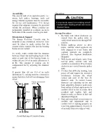
T1 & T2
Discharge Temperature
Sensor
High Voltage Terminals
A1 & A2 Alarm Relay Out
M1 & M2 Contactor
L1
Control Voltage N
L2
Control Voltage L
U1 & U2 Digital Unloader Solenoid
V1 & V2 Vapor Injection Solenoid
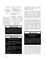
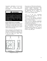
The compressor controller modulates the
compressor unloader solenoid in an on/off
pattern according to the capacity demand
signal of the system. The following table
shows the linear relationship between the
demand signal and compressor capacity
modulation. The compressor controller
protects the compressor against high
discharge temperature. Refer to Appendix B
for the relationship between thermistor
temperature readings and resistance values.
Table 22 - Demand Signal vs. Compressor Capacity Modulation
Demand
Signal (VDC)
Loaded %
Unloaded %
Time Loaded
Time
Unloaded
% Compressor
Capacity
1.00
Off
Off
Off
Off
0%
1.44
10%
90%
1.5 sec
13.5 sec
10%
3.00
50%
50%
7.5 sec
7.5 sec
50%
4.20
80%
20%
12 sec
3 sec
80%
5.00
100%
0%
15 sec
0 sec
100%
Figure 30 - Compressor Controller Flash Code Details
Summary of Contents for RQ NextGen Series
Page 2: ......
Page 26: ...26 Figure 3 RQ Cabinet Standard and Power Exhaust Gasket Locations...
Page 40: ...40 Figure 23 Post Corner Hole Piping Figure 24 Post Back Hole Piping...
Page 88: ...88 Gas Heater Operating Instructions Figure 36 Gas Heater Instructions...
Page 95: ...95...
Page 96: ...96...
Page 105: ...105 Maintenance Log E Coated Coil...
Page 107: ...107...


