


45
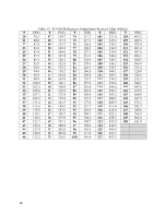
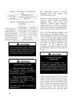
Table 12 - Acceptable Microchannel Air-Cooled Condenser Coil Liquid Sub-Cooling Values
(Imperial)
Cooling Mode Liquid Sub-Cooling Values(°F)
Ambient
(°F)
Evaporator Coil Saturation Temperature (°F)
40
45
48
50
55
67
9 - 14
8 - 13
8 - 13
7 - 12
5 - 10
72
10 - 15
9 - 14
9 - 14
8 - 13
7 - 12
82
10 - 15
10 - 15
10 - 15
9 - 14
7 - 12
95
10 - 15
10 - 15
10 - 15
9 - 14
8 - 13
105
11 - 16
11 - 16
10 - 15
10 - 15
8 - 13
115
10 - 15
11 - 16
11 - 16
11 - 16
9 - 14
Notes:
1.
Microchannel condenser coils are more sensitive to charge. The system must
be running in cooling mode with compressor, supply airflow & condenser fan
speed at full load. The sub-cooling value changes depending on the ambient
temperature reading and the microchannel evaporator coil saturation
temperature. To find the correct sub-cooling value, find the ambient
temperature on the first column and follow that across to the SST (4.4-12.8°C
[40-55°F]).
2.
Superheat for Microchannel condenser coils must be between 4.4 and 8.3°C
(8 - 15°F).
Adjusting Sub-cooling and Superheat
Temperatures
The system is overcharged if the sub-cooling
temperature is too high and the evaporator is
fully loaded (low loads on the evaporator
result in increased sub-cooling) and the
evaporator superheat is within the
temperature range as shown in the table
above (high superheat results in increased
sub-cooling).
Correct an overcharged system by reducing
the amount of refrigerant in the system to
lower the sub-cooling.
The system is undercharged if the superheat
is too high and the sub-cooling is too low
Correct an undercharged system by adding
refrigerant to the system to reduce superheat
and raise sub-cooling.
If the sub-cooling is correct and the superheat
is too high, the TXV may need adjustment to
correct the superheat.
Summary of Contents for RQ NextGen Series
Page 2: ......
Page 26: ...26 Figure 3 RQ Cabinet Standard and Power Exhaust Gasket Locations...
Page 40: ...40 Figure 23 Post Corner Hole Piping Figure 24 Post Back Hole Piping...
Page 88: ...88 Gas Heater Operating Instructions Figure 36 Gas Heater Instructions...
Page 95: ...95...
Page 96: ...96...
Page 105: ...105 Maintenance Log E Coated Coil...
Page 107: ...107...


