


42
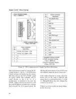
Supply Fan EC Motor Startup
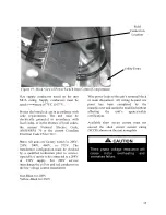
Figure 25 - PIN Connectors on EC Supply Fan Motor Electronics
Speed adjustment is made by varying the DC
voltage on pin 8 (+) & 16 (-). If AAON Orion
Control systems are installed on the system,
then they will provide the 0-10VDC signal
for speed control. The controller will be
wired directly to pin 8 & 16. If a
potentiometer is installed in the unit, the
10VDC output of the motor electronics will
be wired through the potentiometer and then
back into pin 8 & 16 for speed control. By
adjusting the potentiometer from 0-100% you
can manually adjust the speed of the motor.
If the rotation direction is wrong, check the
brown wire on the control connector and
ensure that it is connected from pin 13 to pin
11. Making/Breaking this wire changes the
rotation of the motor.
If there is no rotation and/or no speed change,
try the following:
Summary of Contents for RQ NextGen Series
Page 2: ......
Page 26: ...26 Figure 3 RQ Cabinet Standard and Power Exhaust Gasket Locations...
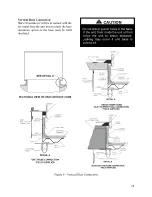
Page 40: ...40 Figure 23 Post Corner Hole Piping Figure 24 Post Back Hole Piping...
Page 88: ...88 Gas Heater Operating Instructions Figure 36 Gas Heater Instructions...
Page 95: ...95...
Page 96: ...96...
Page 105: ...105 Maintenance Log E Coated Coil...
Page 107: ...107...


