


90
Table A1. Armgrip Flange Adapter Details
Valve Size
125 psi/150 psi 250 psi/300 psi
Ductile Iron Bolt Ductile Iron Bolt
No.
Size
No.
Size
2-1/2
4
5/8
8
3/4
3
4
5/8
8
3/4
4
8
5/8
8
3/4
5
8
3/4
8
3/4
6
8
3/4
12
3/4
8
8
3/4
12
7/8
10
12
7/8
16
1
12
12
7/8
16
1-1/8
The gasket cavity should face out to the
adjoining flange.
2.
Lubricate the inner and outer diameter of
the gasket with the lubricant provided or
a similar non-petroleum based water
soluble grease.
3.
Press the gasket firmly into the flange
cavity ensuring that the sealing lip is
pointed outward. When in place, the
gasket should not extend beyond the end
of the pipe (as shown).
4.
Position the adjoining flange or the pipe
to the Armgrip flange adapter and install
the remaining bolts. The two locking
bolts should be tightened first in order to
position the flange correctly.
Note: Care should be taken to ensure that
the gasket is not pinched or bent between
flanges.
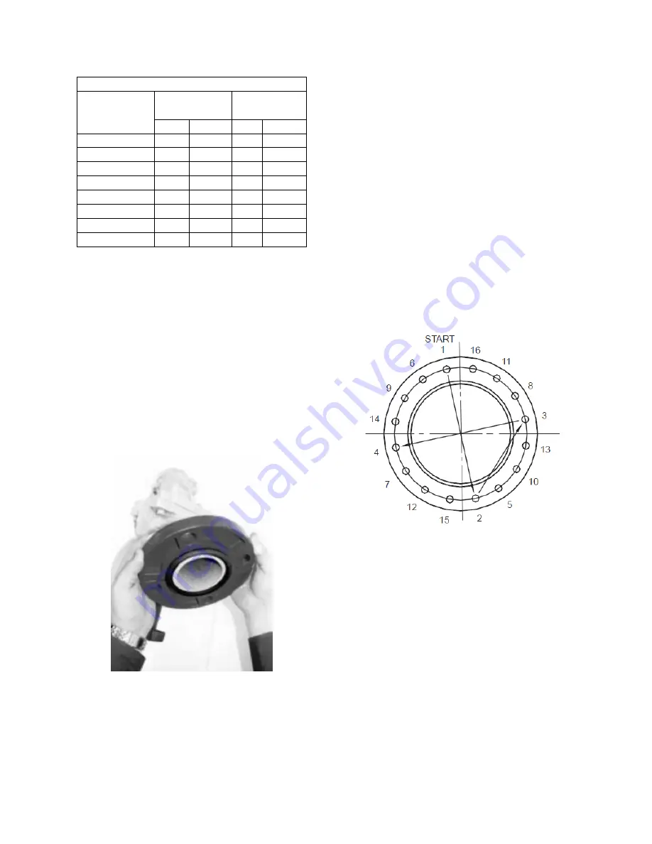
5.
Tighten remaining nuts evenly by
following bolting instructions, so that the
flange faces remain parallel (as shown in
the figure labeled Recommended Bolt
Tightening Procedure). Flange bolts
should be tightened to 70 ft-lbs torque
minimum to assure firm metal to metal
contact. When raised face flanges are
used, there will be a gap between the
faces of the outer diameter.
6.
Flange gaskets are not interchangeable
with other mechanical pipe couplings or
flange gaskets.
Recommended Bolt Tightening Procedure
Field Conversion (Straight to Angle
Pattern Valve:
1.
Open valve at least one complete turn.
2.
Remove the body bolts from valve body
using Allen Key
3.
Rotate one half of the valve body 180°
making sure the lower valve seat and O
ring stay in position. Inspect the O ring
for any cuts or nicks and replace if
necessary.
4.
Replace body bolts and torque evenly to
70 ft-lbs.
Summary of Contents for LZ Series
Page 2: ......
Page 27: ...27 Figure 6 Concrete Pad Mounting with Dimensions Figure 7 LZ Base ...
Page 36: ...36 Figure 17 Typical Flue Vent Piping ...
Page 83: ...83 ...
Page 84: ...84 ...
Page 95: ...95 Flo Trex Cross Section ...