background image


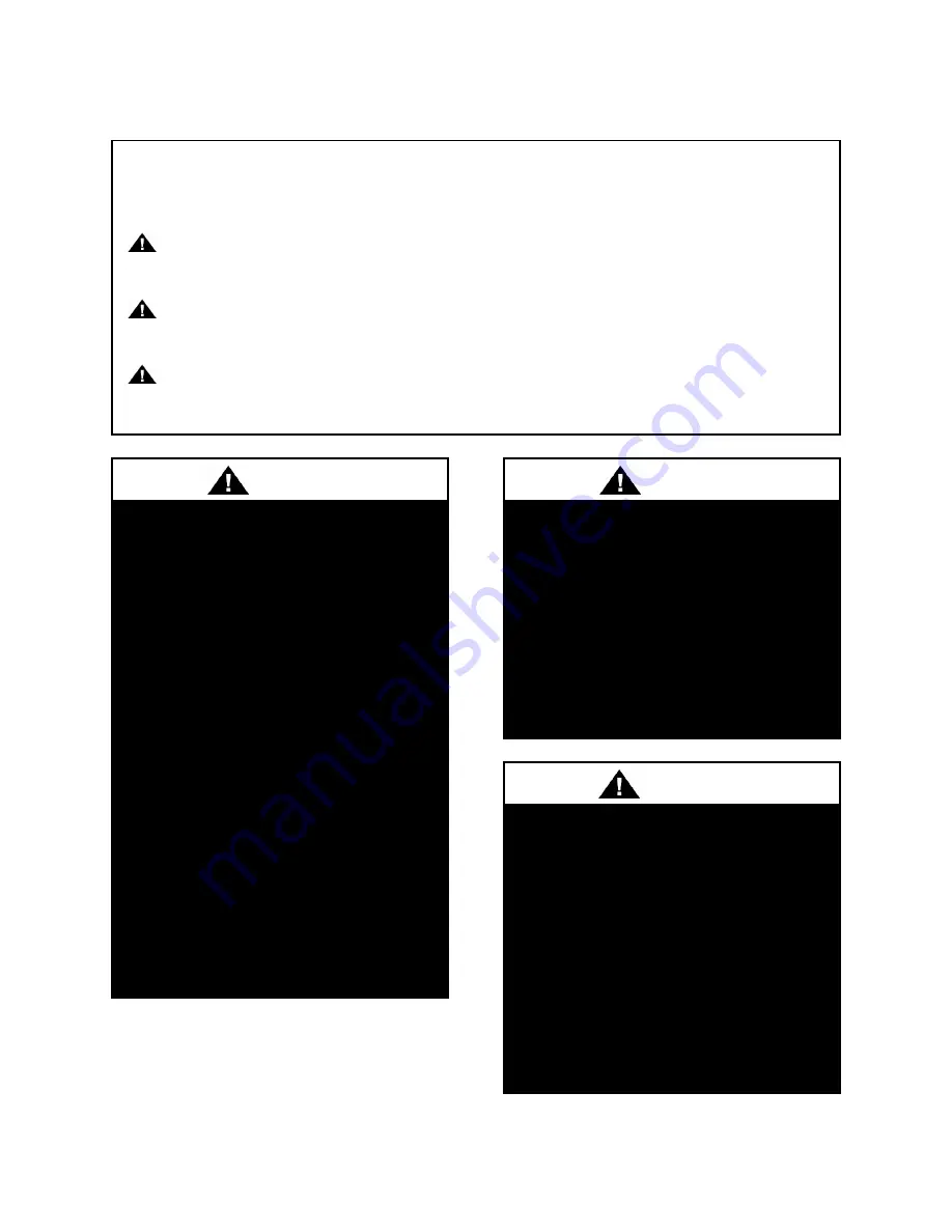
Safety 


Attention should be paid to the following statements: 


NOTE

 - Notes are intended to clarify the unit installation, operation and maintenance. 


CAUTION 

- Caution statements are given to prevent actions that may result in equipment 

damage, property damage, or personal injury.  


WARNING

  -  Warning  statements  are  given  to  prevent  actions  that  could  result  in 

equipment damage, property damage, personal injury or death. 


DANGER

 - Danger statements are given to prevent actions that will result in equipment 

damage, property damage, severe personal injury or death.  


ELECTRIC 

SHOCK, 

FIRE 

OR 

EXPLOSION HAZARD 
 
Failure  to  follow  safety  warnings 
exactly  could  result  in  dangerous 
operation,  serious  injury,  death  or 
property damage.  
 
Improper  servicing  could  result  in 
dangerous  operation,  serious  injury, 
death, or property damage. 
 

Before  servicing,  disconnect  all 
electrical  power  to  the  unit.  More 
than  one  disconnect  may  be 
provided. 

When  servicing  controls,  label  all 
wires 

prior 

to 

disconnecting. 

Reconnect wires correctly. 

Verify  proper  operation  after 
servicing.  Secure  all  doors  with 
key-lock or nut and bolt. 


WARNING


QUALIFIED INSTALLER 

 
Improper 

installation, 

adjustment, 

alteration, service or maintenance can 
cause  property  damage,  personal 
injury  or  loss  of  life.  Startup  and 
service  must  be  performed  by  a 
Factory Trained Service Technician. A 
copy of  this IOM should be kept  with 
the unit. 


WARNING


WHAT TO DO IF YOU SMELL GAS 
 

Do not try to turn on unit.  

Shut off main gas supply. 

Do not touch any electric switch. 

Do  not  use  any  phone  in  the 
building. 

Never  test  for  gas  leaks  with  an 
open flame. 

Use a gas detection soap solution 
and check all gas connections and 
shut off valves. 


CAUTION 


Summary of Contents for LZ Series

Page 1: ... property damage A copy of this IOM should be kept with the unit Do not store gasoline or other flammable vapors and liquids in the vicinity of this or any other appliance WHAT TO DO IF YOU SMELL GAS Do not try to light any appliance Do not touch any electrical switch Do not use any phone in your building Leave the building immediately Immediately call you gas supplier from a phone remote from the...

Page 2: ......

Page 3: ...Exhaust Fan 29 Water Connection 30 Temporary Drain Evaporative Condenser 31 Access Doors 31 End Flashing Installation 31 Boiler Gas Connection 32 Boiler Air Intake Vent Piping 32 Sidewall Direct Boiler Venting 35 Vertical Direct Boiler Venting 37 Boiler Condensate Drain 41 Split Unit Assembly 41 Unit Mounting Isolation 41 Low Ambient Operation 41 Electrical 42 Variable Speed Compressors 44 Condens...

Page 4: ...equence of Operation for LZ Series units with Diagnostics 66 Pump Maintenance 67 Fan Motor Maintenance 67 Access Doors 67 Bearings Lubrication 68 Recommended Monthly Inspection 68 Mist Eliminators 68 Air Inlet 68 Stainless Steel Base Pan 68 Propeller Fans and Motors 68 Recommended Annual Inspection 68 Cleaning 68 Water Quality 69 Mechanical Cleaning 70 Service 70 Replacement Parts 70 Water Pressur...

Page 5: ... Table 14 R 410A Refrigerant Temperature Pressure Chart 56 Table 15 Recirculating Water Quality Guidelines 69 Figures Figure 1 Backflow Preventer 23 Figure 2 Pressure Relief Valve 24 Figure 3 Curb Mounting with Dimensions 26 Figure 4 Curb End Detail 26 Figure 5 Steel Mounting Rail with Dimensions 26 Figure 6 Concrete Pad Mounting with Dimensions 27 Figure 7 LZ Base 27 Figure 8 Lifting Points 28 Fi...

Page 6: ...ction Layout 45 Figure 27 Fan with the HUB on the top and RET on the bottom 48 Figure 28 Bushing Mount Location 48 Figure 29 RET with Pin in Groove 4 48 Figure 30 Fan HUB and RET Castings 48 Figure 31 Pitch Insert 49 Figure 32 Replaceable Core Filter Driers 52 Figure 33 Proper Unit Location 62 Figure 34 Improper Unit Locations 62 Figure 35 Water Makeup Valve 65 Figure 36 Evaporative condenser acce...

Page 7: ...t Non Fused Disconnect Power Switch Factory Installed Refrigerant Leak Detector Water Piping Air Separator Waterside Thermometer and Pressure Gauge Installation and Maintenance Double Wall Rigid Polyurethane Foam Injected Panel Construction Lighted Walk In Service Vestibule Access Doors with Full Length Stainless Steel Piano Hinges Zinc Cast Lockable Handles Factory Installed Convenience Outlet Se...

Page 8: ...ould result in dangerous operation serious injury death or property damage Before servicing disconnect all electrical power to the unit More than one disconnect may be provided When servicing controls label all wires prior to disconnecting Reconnect wires correctly Verify proper operation after servicing Secure all doors with key lock or nut and bolt WARNING QUALIFIED INSTALLER Improper installati...

Page 9: ...ulation requiring an Arc Flash Boundary to be field established and marked for identification of where appropriate Personal Protective Equipment PPE be worn should be followed WARNING GROUNDING REQUIRED All field installed wiring must be completed by qualified personnel Field installed wiring must comply with NEC CEC local and state electrical code requirements Failure to follow code requirements ...

Page 10: ...ygen acetylene or air in place of refrigerant and dry nitrogen for leak testing A violent explosion may result causing injury or death WARNING PVC Polyvinyl Chloride and CPVC Chlorinated Polyvinyl Chloride are vulnerable to attack by certain chemicals Polyolester POE oils that are used in R 410A and other refrigerant systems will cause stress cracking of PVC or CPVC piping even if only present in ...

Page 11: ...wo types of lubricants used with R 410A and R134a refrigeration systems Refer to the compressor label for the proper compressor lubricant type CAUTION Do not clean DX refrigerant coils with hot water or steam The use of hot water or steam on refrigerant coils will cause high pressure inside the coil tubing and damage to the coil CAUTION Rotation must be checked on ALL MOTORS AND COMPRESSORS of 3 p...

Page 12: ... Capacity 240 240 ton Capacity 274 274 ton Capacity 300 300 ton Capacity 319 319 ton Capacity 356 356 ton Capacity 360 360 ton Capacity 401 401 ton Capacity 441 441 ton Capacity 450 450 ton Capacity 478 478 ton Capacity 540 540 ton Capacity Series Scroll Compressor Air Cooled A 45 60 ton units B 75 ton unit C 95 140 ton units D 170 200 ton units Evaporative Condensed A 53 69 ton units B 78 ton uni...

Page 13: ...s 2 Pumping Style 0 No Pumps A Const Primary Pumping System Small Pipe Size B Const Primary Pumping System Large Pipe Size C Var Primary Pumping System Small Pipe Size D Var Primary Pumping System Large Pipe Size E Primary Secondary Pumping System Small Pipe Size F Primary Secondary Pumping System Large Pipe Size 3A Building Pump Configuration 0 No Building Pumps A 1 Pump High Eff Motor B 1 Dual P...

Page 14: ...5x5x11 5 1 6x6x11 5 2 8x8x11 5 3 4x4x13 4 6x6x13 5 8x8x13 3D Building Pump Motor Size 0 No Building Pumps A 0 5 hp B 0 75 hp C 1 hp D 1 5 hp E 2 hp F 3 hp G 5 hp H 7 5 hp J 10 hp K 15 hp L 20 hp M 25 hp 3D Building Pump Motor Size Continued N 30 hp P 40 hp Q 50 hp R 60 hp S 75 hp 4A Recirculating Pump Configuration 0 No Recirculating Pumps A 1 Pump High Eff Motor B 1 Dual Pump High Eff Motors C 2 ...

Page 15: ...x13 4 6x6x13 5 8x8x13 4D Recirculating Pump Motor Size 0 No Recirculating Pumps A 0 5 hp B 0 75 hp C 1 hp D 1 5 hp E 2 hp F 3 hp G 5 hp H 7 5 hp J 10 hp K 15 hp L 20 hp M 25 hp 4D Recirculating Pump Motor Size Continued N 30 hp P 40 hp Q 50 hp R 60 hp S 75 hp 5A Boiler Building Pump Configuration 0 No Boiler Pumps 5B Boiler Building Pump Series RPM 0 No Boiler Pumps 5C Boiler Building Pump Size 0 ...

Page 16: ...nostics N LonTalk with Diagnostics 11 Cabinet Options 0 None B Access Door Windows 12 Vestibule Accessories 0 None A Refrigerant Leak Detector B Motorized Service Vestibule Fresh Air C Vestibule Heating Electric D Vestibule Cooling Fan Coil F Option A B G Option A C 12 Vestibule Accessories Continued H Option A D K Option B C L Option B D N Option C D R Option A B C S Option A B D U Option A C D Y...

Page 17: ...V D AX 60V E AX 80V F AX 100V G AX 120V H AX 180V J AX 200V K AX 240V L AX 260V M AX 280V 22 Boiler Compression Tank 0 None 23 Blank 0 Standard 24 Chiller Accessories 0 None A Glycol chiller B Air Separator C Thermometers Pressure Gauges D Chemical Pot Feeder E Auto Glycol Feeder F Option A B G Option A C H Option A D J Option A E K Option B C L Option B D 24 Chiller Accessories Continued M Option...

Page 18: ... 30 31 32 33 34 35 18 27 Blank 0 Standard 28 Blank 0 Standard 29 Blank 0 Standard 30 Blank 0 Standard 31 Blank 0 Standard 32 Blank 0 Standard 33 Warranty 0 Standard Warranty D Compressor Warranty Years 2 5 34 Cabinet Material D Galvanized Cabinet 6 Base Rail Double Slope Roof H Galvanized Cabinet 8 Base Rail Double Slope Roof 35 Paint Special Pricing Authorizations B Premium AAON Gray Paint Exteri...

Page 19: ...al Code CSA C22 1 Receiving Unit When received the unit should be checked for damage that might have occurred in transit If damage is found it should be noted on the carrier s Freight Bill A request for inspection by carrier s agent should be made in writing at once Nameplate should be checked to ensure the correct model sizes and voltages have been received to match the job requirements Improper ...

Page 20: ...cept for complete shutdown When power is cut off from the unit any compressors equipped with crankcase heaters cannot prevent refrigerant migration This means the compressor will cool down and liquid refrigerant may accumulate in the compressor The compressor is designed to pump refrigerant gas and damage may occur when power is restored if liquid enters the compressor COMPRESSOR CYCLING 3 MINUTE ...

Page 21: ...al for specific details Chiller Primary Pumping Primary pumping uses a single pump to move water or glycol through the chiller evaporator and back to the building This pumping package provides a constant or variable flow of water to the building The pump is activated whenever the chiller is given a run signal Water enters the unit through the return water piping and then travels through an air sep...

Page 22: ...ry loop increases above the flow in the primary loop excess flow bypasses the chiller and circulates through the bypass water line The secondary pump has its own suction guide combination valve and isolation valve similar to the primary pump with the addition of an air separator to remove any air that is entrapped in the water Condensing Boilers AAON LZ chillers are available with factory installe...

Page 23: ...g could occur in the piping or the pump could cavitate There is an isolation valve on the inlet and outlet of the pressure reducing valve for service The pressure reducing valve fills the system at a reduced rate There is a bypass around the pressure reducing valve for the initial fill of the system to increase the initial fill speed After the initial system fill this valve should be closed Compre...

Page 24: ...the discharge port to prevent liquid recirculation when only one pump is operating Isolation valves in the casing allow one pump to be isolated and removed for service while the other pump is still operating When redundant pumping is required with high flow rates two independent pumps may be installed in parallel Each pump will have its own suction guide strainer combination valve and isolation va...

Page 25: ...condensing section Consideration must be given to obstruction caused by snow accumulation when placing the unit Curb and Steel Mount Installation Make openings in the roof decking large enough to allow for water piping electrical and gas penetrations and workspace only Do not make openings larger than necessary Set the curb to coincide with the openings Make sure curb is level If an LZ with air co...

Page 26: ...26 Figure 3 Curb Mounting with Dimensions Figure 4 Curb End Detail Figure 5 Steel Mounting Rail with Dimensions ...

Page 27: ...27 Figure 6 Concrete Pad Mounting with Dimensions Figure 7 LZ Base ...

Page 28: ...ler make sure the tank is empty before lifting Secure hooks and cables at all lifting points lugs provided on the unit Hoist unit to a point directly above the curb or mounting rail Be sure that the gasket material has been applied to the curb or mounting rail Carefully lower and align unit with utility openings Lower the unit until the unit skirt fits around the curb Make sure the unit is properl...

Page 29: ...t all marked lifting points Vestibule Exhaust Fan Prior to unit operation of units with service vestibules the exhaust fan shipping support must be removed from the exterior of the unit The exhaust fan also includes a factory provide exterior rain hood which must be installed Figure 10 Vestibule Exhaust Fan ...

Page 30: ...llation The chiller must be operated only with liquid flowing through the evaporators WARNING Boilers must be operated only with liquid flowing through the boiler WARNING PVC Polyvinyl Chloride and CPVC Chlorinated Polyvinyl Chloride are vulnerable to attack by certain chemicals Polyolester POE oils used with R 410A and other refrigerants even in trace amounts in a PVC or CPVC piping system will r...

Page 31: ...e evaporator and pumping package compartment See Figure 36 for information on leak checking these doors End Flashing Installation On all LZ Series units the cabinet width will overhang the shipping trailer on each side In order to secure and protect the unit during transit the sheet metal end flashings have been removed from the unit The slot created at the base of each end of the unit allows the ...

Page 32: ...5 psig 14 W C Some leak test solutions including soap and water may cause corrosion These solutions should be rinsed off with water after testing Boiler Air Intake Vent Piping Each boiler requires the installation of air intake and vent piping This piping has been removed for shipping purposes All piping must be reinstalled according to the instructions provided in this section prior to boiler ope...

Page 33: ...T A 4 C or D C 4 2 400 2 5 psi 2 NPT A 1 C or D D KBN701 1 700 6 14 W C 1 1 2 NPT A 2 C or D D 2 1 400 6 14 W C 2 NPT A 3 C or D D 3 2 100 2 5 psi 2 NPT A 4 C or D D 4 2 800 2 5 psi 2 NPT A 1 C or D F KBN801 1 800 6 14 W C 1 1 2 NPT A 2 C or D F 2 1 600 6 14 W C 2 NPT A 3 C or D F 3 2 400 2 5 psi 2 NPT A 4 C or D F 4 3 200 2 5 psi 2 NPT A 1 C or D G SBN1000 1 1 000 6 14 W C 1 1 2 NPT A 2 C or D G ...

Page 34: ...8 000 2 5 psi 3 Flange A 1 C or D L FBN2500 1 2 500 2 5 psi 1 1 2 NPT A 2 C or D L 2 5 000 2 5 psi 2 NPT A 3 C or D L 3 7 500 2 5 psi 3 Flange A 4 C or D L 4 10 000 2 5 psi 3 Flange A 1 C or D M FBN3000 1 3 000 2 5 psi 1 1 2 NPT A 2 C or D M 2 6 000 2 5 psi 2 NPT A 3 C or D M 3 9 000 2 5 psi 3 Flange A 4 C or D M 4 12 000 2 5 psi 3 Flange A 1 C or D N FBN3500 1 3 500 2 5 psi 2 NPT A 2 C or D N 2 7...

Page 35: ...ler access door remove the shipping cover and attach the sidewall vent plate shipped with the unit Figure 14 Sidewall Vent Shipping Cover Removal Figure 15 Sidewall Vent Plate Installation 2 Attach air intake piping to the air inlet connector on the boiler at one end and run through the sidewall of the unit at the other end All air intake pipes and fittings are PVC Figure 16 Typical Air Intake Pip...

Page 36: ...36 Figure 17 Typical Flue Vent Piping ...

Page 37: ...less steel screws Seal all gaps between the pipes and the sidewall Seal around the sidewall vent base to the wall ensuring no air gaps 5 Assemble vent cap to vent base and securely attach using stainless steel screws Figure 18 Sidewall Vent Base Figure 19 Sidewall Vent Cap Vertical Direct Boiler Venting For units with Lochinvar Crest boilers feature B4 K L M or N the air intake and vent piping is ...

Page 38: ...ng use only primer and cement approved for use with PVC ANSI ASTM D2564 WARNING JOINT CONNECTIONS The female end of each component incorporates a sealing gasket and a mechanical locking bond Examine all components prior to installation Gaskets must be in proper position to prevent leakage CAUTION For units with stainless steel piping all components must be installed in accordance with the manufact...

Page 39: ...run vertically through the roof of the unit All vent pipes and fittings will be stainless steel components 6 The air intake piping must terminate in a down turned 180 return pipe no further than 2 feet horizontally from the center of the vent pipe The placement avoids recirculation of flue products into the combustion air stream 7 The vent piping must terminate in an up turned coupling with the to...

Page 40: ...40 Figure 24 Typical Vertical Vent Piping Figure 25 Vertical Termination of Air Intake and Vent Piping ...

Page 41: ...the connection location can be used to align the top of the two sections 6 When the two sections are properly aligned the provided splice parts should be installed There is one internal splice on the base seam and external splices for the roof and both side panels Before installing the side panel splices polyurethane caulking should be applied to the top 6 of the panel joint starting at the bottom...

Page 42: ...control field wiring as shown on the unit specific wiring diagram provided with the unit Size supply conductors based on the unit MCA rating Supply conductors must be rated a minimum of 167 F 75 C Route power and control wiring separately through the utility entry Do not run power and signal wires in the same conduit Power and signal wires in the same conduit can cause electrical interference Tabl...

Page 43: ...ent should not exceed the short circuit current rating SCCR shown on the unit nameplate CONVENIENCE OUTLETS AND SERVICE LIGHTS Convenience outlet and service light circuits are wired to the incoming power side of the disconnect These circuits will remain powered even when unit disconnect is off WARNING Installing Contractor is responsible for proper sealing of the electrical and gas entries into t...

Page 44: ...eld Piping Connections There are at least two field water connections that must be made for the evaporative condensed chiller There is a 3 4 MPTF copper fitting city make up water connection and a 2 PVC socket drain connection as shown in Figure 26 This drain should connect to a sanitary sewer or other code permitted drain These connections can go through the base or the wall of the unit There is ...

Page 45: ...e building A field cutout must be made in the wall if the evaporative condensed chiller piping is to go through the unit wall This cutout must be sealed once the piping is installed to prevent water from leaking into the unit Figure 26 Evaporative Condensed Chiller Section Layout Including Field Water Connections and Base Cutout ...

Page 46: ...m the compressors 5 Verify that the rotation of all pumps motors and compressors are correct The rotations have been checked at the factory so if any motors that are not powered by a Variable Frequency Drive are operating backwards two phases should be switch at the unit power connection 6 Verify that any remote stop start device or BMS signal is connected to the chiller controller and requesting ...

Page 47: ...lancing valves on each heat exchanger Flow should be balanced between the two evaporators by a hydronic systems balancing professional Note For more information on programming the controller refer to the MCS Controller manual provided with the chiller Condenser Fan Pitch Adjustment Units installed at elevations above 2 000 feet may require adjustment of the condenser fan pitch to achieve optimal p...

Page 48: ...n The bushing mount is the center section of the hub through which the fan is mounted to the shaft and typically contains either setscrews or a center tapered hole where the bushing inserts Location A is with the bushing mount on air inlet side of the fan Location B is with the bushing mount on air discharge side of the fan Figure 28 Bushing Mount Location 4 Determine the pin location groove Disas...

Page 49: ...lace any balancing weights in their previous locations Tighten bolts in a cross pattern to 5 6 ft lbs of torque Multi Wing W Series Black Glass Reinforced Polypropylene Fan Blade Pitch Angle Setting Instructions Contact your local AAON representative to acquire the new pitch pins for the fan blades Note original position of retaining plates center boss and all hardware including additional hardwar...

Page 50: ...cy Drive are operating backwards two phases should be switch at the unit power connection 6 Verify that any remote stop start device or BMS signal is connected to the chiller controller and requesting the boiler system to start 7 A building load of at least 25 of the boiler capacity should be present in order to properly check operation 8 Complete the general check list at the top of the startup f...

Page 51: ...can be reset based on the ambient air temperature The default temperature target is 135 F with a minimum of 90 F and a maximum of 180 F 4 Each boiler will control its own individual pumps or valves as necessary as they are staged on and off Maintenance General Qualified technicians must perform routine service checks and maintenance This includes reading and recording the condensing and suction pr...

Page 52: ... refrigerant circuit contains a liquid line replaceable core filter drier Replacement is recommended when there is excessive pressure drop across the assembly or moisture is indicated in a liquid line sight glass Figure 32 Replaceable Core Filter Driers Table 11 Filter Drier Maximum Pressure Drop Circuit Loading Max Pressure Drop 100 10 psig 50 5 psig The filter driers are provided with pressure t...

Page 53: ...ass must have the hot gas bypass valve closed to get the proper charge After adding or removing charge the system must be allowed to stabilize typically 10 15 minutes before making any other adjustments The type of unit and options determine the ranges for liquid sub cooling and evaporator superheat Refer to Table 12 when determining the proper sub cooling Prior to filter core service a service ma...

Page 54: ...pressor running Inadequate suction superheat can allow liquid refrigerant to return to the compressors which will wash the oil out of the compressor Lack of oil lubrication will destroy a compressor Liquid sub cooling should be measured with both compressors in a refrigeration system running Compare calculated superheat to Table 12 for the appropriate unit type and options Table 12 Acceptable Refr...

Page 55: ... 27 24 75 79 124 181 28 25 77 82 126 186 30 26 79 85 127 191 32 28 81 88 129 197 34 30 82 91 131 202 36 31 84 94 133 207 37 33 86 97 135 213 39 34 88 100 136 218 41 36 90 104 138 224 43 38 91 107 140 229 45 40 93 111 142 235 46 42 95 114 144 241 48 44 97 118 145 247 50 46 99 121 147 253 52 48 100 125 149 260 54 50 102 129 151 266 55 52 104 133 153 272 57 54 106 137 154 279 59 56 108 141 156 286 61...

Page 56: ...0 96 8 60 169 6 90 273 5 120 416 9 150 611 9 31 98 8 61 172 5 91 277 6 121 422 5 32 100 9 62 175 4 92 281 7 122 428 2 33 102 9 63 178 4 93 285 9 123 433 9 34 105 0 64 181 5 94 290 1 124 439 6 35 107 1 65 184 5 95 294 4 125 445 4 36 109 2 66 187 6 96 298 7 126 451 3 37 111 4 67 190 7 97 303 0 127 457 3 38 113 6 68 193 9 98 307 5 128 463 2 39 115 8 69 197 1 99 311 9 129 469 3 40 118 1 70 200 4 100 3...

Page 57: ...e coils entering air side then surface loaded fibers or dirt should be removed with a vacuum cleaner If a vacuum cleaner is not available a soft non metallic bristle brush may be used In either case the tool should be applied in the direction of the fins Coil surfaces can be easily damaged fin edges bent over if the tool is applied across the fins Use of a water stream such as a garden hose agains...

Page 58: ...ess to the coil s to be cleaned 4 Using a pump up sprayer fill to the appropriate level with potable water and add the correct amount of approved cleaner as per manufacture instructions leaving room for the pump plunger to be reinserted NOTE Coils should always be cleaned back flushed opposite of airflow to prevent impacting the dirt into the coil 5 If the coils have heavy dirt fibers grass leaves...

Page 59: ...able water 2 56 ounces of Chlor rid to 1 gal of water Using a pump up sprayer fill to the appropriate level with potable water and add the correct amount of CHLOR RID salt remover leaving room for the pump plunger to be reinserted 2 Apply CHLOR RID to all external coil surfaces using a pressurized pump up sprayer maintaining a good rate of pressure and at a medium size nozzle spray not a solid str...

Page 60: ...Green is available from AAON Parts and Supply Part T10701 and is biodegradable with a neutral 6 5 pH Recommendation is to use it at a 4 to 1 mix Use the following procedure 1 Rinse the coil completely with water Use a hard spray but be careful not to bend or damage the fins A spray that is too hard will bend the fins Spray from the fan side of the coil 2 With a pump sprayer filled with a mix of 4 ...

Page 61: ...N warranty and service department Use of unapproved chemicals will void the warranty AAON testing has determined that unless a chemical has a neutral pH 6 8 it should not be used Beware of any product that claims to be a foaming cleaner The foam that is generated is caused by a chemical reaction to the aluminum fin material on tube and fin coils and with the fin tube and coating material on microc...

Page 62: ...o prevent the air discharge from entering fresh air intakes or to avoid allowing contaminated building exhaust from entering the condenser Figure 33 Proper Unit Location Follow local and national codes in locating the evaporative condensed chiller but as minimum the sump must be 15 feet from the nearest intake Figure 34 Improper Unit Locations Performance Improper location of the evaporative conde...

Page 63: ...sed chiller or compressors without installation of proper water treatment chemicals Contact your local water treatment expert for correct selection of water treatment chemical adjustment of chemical feed and bleed rates Reverse osmosis and deionized water is corrosive and cannot be used on the LZ Evaporative Condensed Chillers Cleanliness Dirt and debris may accumulate in the sump during shipping ...

Page 64: ...tly mounted to the motor shaft and the motor mounting bolts are aligned and secure Water Make Up Valve The sump water level is controlled by a set of conductivity probes at different levels in the sump The standard sump water level is 15 inches deep This water level controller is located in the vestibule behind the condenser pump There are four conductivity probes in this controller There is a ref...

Page 65: ...ent organisms from becoming resistant to one chemical The mineral content of the water must be controlled All make up water has minerals in it As water is evaporated from the condenser these minerals remain As the mineral content of the water increases the conductivity of the water increases The water treatment controller monitors this conductivity As the water conductivity rises above set point t...

Page 66: ...the condenser fans An outside air thermostat does not allow the condenser to operate when the ambient temperature is below 35 F Sequence of Operation for LZ Series units with Diagnostics These units operate the same way as described in the previous section except the unit controller operates the evaporative condensed chiller These units can also operate down to 0 F when equipped with the low ambie...

Page 67: ...ater is found around the access doors adjust door for tightness Adjust as necessary until leaking stops when door is closed The evaporative condenser doors have an adjustable fit design A good seal and fit are key to avoid leaks A leak inspection is recommended during installation and every six 6 months thereafter If a leak is found use the following steps to adjust the fit of the door This proces...

Page 68: ...g or service Air Inlet Inspect the air inlet louvers and mist eliminators into the condenser section on a monthly basis to remove any paper leaves or other debris that may block the airflow Stainless Steel Base Pan The base pan under the tube bundles is stainless steel and may sometimes become tarnished due to contamination These surfaces should be inspected yearly to ensure they remain clean of a...

Page 69: ...culated water to keep the water quality within the above listed parameters This device is located on the discharge side of the pump It is important to note that since bleed rate is a function of evaporation rate i e amount of heat rejected if the bleed setting is manual based on design heat load too much water will be removed when the heat load is less that design The AAON evaporative condensed ch...

Page 70: ...ter treatment expert for recommendations on chemical cleaning procedures Service If the unit will not operate correctly and a service company is required only a company with service technicians qualified and experienced in both refrigerant chillers and air conditioning are permitted to service the systems to keep warranties in effect If assistance is required the service technician must contact AA...

Page 71: ...pit installations Integral stainless steel strainer Replaceable seat module Bronze body construction Serviceable in line High temperature resistant reinforced diaphragm for hot water Low pressure range 10 35psi 69 241 kPa Materials Body Bronze Seat Replaceable stainless steel Integral Strainer Stainless steel Diaphragm Reinforced EPDM Valve Disc EPDM Standards Meets requirements of ASSE Standard 1...

Page 72: ...ssure is higher than the set pressure under no flow conditions the cause could be thermal expansion pressure creep or dirt debris on the seat Thermal expansion occurs whenever water is heated in a closed system The system is closed when supply pressure exceeds 150 psi or a check valve or backflow preventer is installed in the supply piping To determine if this is the result of thermal expansion tr...

Page 73: ...purge air that may be in the water system The vent valve utilizes a float to actuate the valve plug which is located at the top of the valve Once the air is displaced and the system pressure is sustained the valve plug seals and prevents any water from escaping from the system The float vent can also operate as an anti vacuum device since it will permit air to enter the system when it must be drai...

Page 74: ... not be vented while the fluid is circulating in the system but it can vent when the system is shut off The figure below shows the installation of the vent valve for the venting of air while the fluid is circulating in the system and the required increase in pipe size in order to obtain proper separation of air from water The valve should be mounted only in a vertical position as its operation is ...

Page 75: ... be read and understood by installing operating and maintenance personnel The equipment supplied has been designed and constructed to be safe and without risk to health and safety when properly installed operated and maintained The instructions following must be strictly adhered to If clarification is needed on any point please contact Armstrong quoting the equipment serial number Where under norm...

Page 76: ...acking the casing with moisture absorbing material and covering the flanges is acceptable When returning to service be sure to remove the drying agent from the pump Handling Large VIL Units One effective way of lifting a large pumping unit is to place lifting hooks through the motor lifting rings or straps around the upper part of the motor The pump and motor unit will free stand on the casing rib...

Page 77: ... with the directional arrow on the pump casing To reverse rotation of a three phase motor interchange any two power leads Start the pump with the discharge valve closed and the suction valve open and then gradually open the discharge valve when the motor is at operating speed The discharge valve may be cracked or open slightly at start up to help eliminate trapped air When stopping the pump Close ...

Page 78: ... the unit starting while being serviced must be eliminated If mechanical seal environmental accessories are installed ensure water is flowing through the sight flow indicator and that filter cartridges are replaced as recommended Lubrication Pump Lubrication is not required There are no bearings in the pump that need external lubrication service Large Series split coupled units are installed with ...

Page 79: ...nical seals may weep slightly at start up Allow the pump to continue operating for several hours and the mechanical seal to seat properly prior to calling for service personnel System Cleanliness Before starting the pump the system must be thoroughly cleaned flushed and drained and replenished with clean liquid Welding slag and other foreign materials Stop Leak and cleaning compounds and improper ...

Page 80: ... locked in the center position This is indicated by both locking handles in the vertical position and the center pin of the locking arms 4 locked by the handles This procedure allows the discharge flapper valves to pivot freely and locks the suction valve firmly in the center position Procedure for Isolation of One Side 1 Stop the pump to be serviced 2 Close and lock the suction and discharge valv...

Page 81: ...t in injury to the operator and or damage to the pump Locking 1 Loosen discharge side set screw 11 to release the locking handle 3 2 Rotate the discharge side locking handle 3 so that the handle points toward the pump to be serviced and secure in the horizontal position using set screw 11 This releases the discharge locking arm 4 3 Rotate discharge valve shaft 16 towards the pump to be isolated Th...

Page 82: ...se the locking handle 3 so that the cam on the base on the handle forces the pin of the locking arm 4 towards the pump to be isolated The locking handle 3 should be raised to between 45 degrees and the vertical position This handle should not be rotated past the vertical position 5 Tighten set screw 11 to secure the locking handle 3 in position Unlocking 1 Open the interconnecting valve on the sea...

Page 83: ...83 ...

Page 84: ...84 ...

Page 85: ...k and adjust the charge pressure by adding or releasing air for each application Note If the system has been filled the tank must be isolated from the system and the tank emptied before charging This ensures all fluid has exited the diaphragm area and proper charging will occur If the pre charge adjustment is necessary oil and water free compressed air or nitrogen gas may be used Check the pre cha...

Page 86: ... The Suction Guides may be installed in any arrangement feasible the arrangement of the pump flange bolt holes Inspection Suction Guides are thoroughly tested and inspected before shipment to assure they meet with your order requirements All units must be carefully examined upon arrival for possible damage during transit Any evidence of mishandling should be reported immediately to the carrier and...

Page 87: ...nit When the system pressure drops below the set point on the pressure switch the GLA pump is started adding fluid from the GLA tank into the HVAC system When the system pressure returns to normal operating conditions the pump stops As the tank empties a level switch is actuated preventing the pump from running dry Ultra Unit When the system pressure drops below the set point on the pressure switc...

Page 88: ...l the contacts change The high system pressure switch should first be set higher than the required pressure by turning the screw clockwise and the setting then made by turning the screw counter clockwise until the switch contacts changeover The other switches should first be set lower than the required pressure by turning the screw counter clockwise and the setting then made by turning the screw c...

Page 89: ...mixing tank is calibrated in liters and US gallons The normal top up level is 53 US gallons 200 liters 1 Calculate the amount of water needed and add or drain to the correct level 2 Add the required amount of glycol 3 Operate the manual agitating switch 4 Check the mixture percentage The unit is now ready for service Flo Trex Combination Valve Introduction The Flo Trex combination valves are desig...

Page 90: ...der to position the flange correctly Note Care should be taken to ensure that the gasket is not pinched or bent between flanges 5 Tighten remaining nuts evenly by following bolting instructions so that the flange faces remain parallel as shown in the figure labeled Recommended Bolt Tightening Procedure Flange bolts should be tightened to 70 ft lbs torque minimum to assure firm metal to metal conta...

Page 91: ... With valve in fully open position locate the pressure differential on left hand side of the Flo Trex Performance Curve with Valve in Full Open Position chart and extend line horizontally across to valve size being used Drop line vertically down and read flow rate from bottom of chart Safety glasses should be worn Probes should not be left inserted into fittings for long periods of time as leakage...

Page 92: ...e and stem position using the flow indicator scale Calculate the percentage of valve opening based on the number of rings at the fully open position Valve Size 2 1 2 3 4 5 6 8 10 12 Number of Rings 5 5 6 9 10 12 18 28 valve fully open Step 3 Measure and record the differential pressure across the valve in the throttled position Step 4 Locate percentage of valve opening on the bottom scale of Inher...

Page 93: ...hrottled position with more than 25 ft pressure differential Instead the pump impeller should be trimmed or valves located elsewhere in the system to partially throttle the flow Operation To assure tight shut off the valve must be closed using a wrench with 25 to 30 ft lbs of torque To assure trouble free check valve operation and shut off operation the valve should be periodically opened and clos...

Page 94: ...1 Drain the system and remove valve from piping Step 2 Remove the body bolts from the body using an Allen Key Step 3 Remove seat and O Ring O rings are not used on valves of 8 inches or larger Step 4 Inspect and clean O ring cavity and install new O ring and seat Valve disc stem should be inspected and replaced if worn Valve stem O ring should be replaced at this time as discussed under Repacking ...

Page 95: ...95 Flo Trex Cross Section ...

Page 96: ...tor should verify the following items 1 Is there any visible shipping damage Yes No 2 Is the unit level Yes No 3 Are the unit clearances adequate for service and operation Yes No 4 Do all access doors open freely and are the handles operational Yes No 5 Have all shipping braces been removed Yes No 6 Have all electrical connections been tested for tightness Yes No 7 Does the electrical service corr...

Page 97: ...oad Yes No 7 Has the water piping been insulated Yes No 8 Is the glycol the proper type and concentration N A if water Yes No 9 What is the freeze point of the glycol N A if water ______________________________ Chiller Configuration Air Cooled Chiller Evaporative Condensed Chiller Low Ambient Control Condenser Safety Check No Water Leaks Water Flow ________ gpm Chilled Water In Temperature _______...

Page 98: ... Saturated Temperature Line Temperature Sub cooling Superheat Discharge N A N A Suction N A Liquid N A Refrigeration System 2 Cooling Mode Pressure Saturated Temperature Line Temperature Sub cooling Superheat Discharge N A N A Suction N A Liquid N A Refrigeration System 3 Cooling Mode Pressure Saturated Temperature Line Temperature Sub cooling Superheat Discharge N A N A Suction N A Liquid N A ...

Page 99: ... N A Suction N A Liquid N A Refrigeration System 6 Cooling Mode Pressure Saturated Temperature Line Temperature Sub cooling Superheat Discharge N A N A Suction N A Liquid N A Refrigeration System 7 Cooling Mode Pressure Saturated Temperature Line Temperature Sub cooling Superheat Discharge N A N A Suction N A Liquid N A Refrigeration System 8 Cooling Mode Pressure Saturated Temperature Line Temper...

Page 100: ...Condenser Fans Alignment Check Rotation Nameplate Amps________ Number hp L1 L2 L3 1 2 3 4 5 6 7 8 9 10 11 12 13 14 15 16 17 18 19 20 21 22 23 24 Condenser Pumps Check Rotation Number hp L1 L2 L3 1 2 ...

Page 101: ...r Pump 2 Chiller Pump 3 Chiller Pump 4 Chiller Building Pump 1 Chiller Building Pump 2 Boiler Building Pump 1 Boiler Building Pump 2 Boilers Boiler Water In Temperature ________ F Boiler Water Out Temperature ________ F Boiler Amps Boiler Amps 1 2 3 4 5 6 7 8 ...

Page 102: ...ument any service repair or adjustments AAON Service and Warranty Departments are available to advise and provide phone help for proper operation and replacement parts The responsibility for proper start up maintenance and servicing of the equipment falls to the owner and qualified licensed technician Entry Date Action Taken Name Tel ...

Page 103: ...onized water cannot be used in the evaporative cooled condensing units Added suction line filter removal instructions May 2018 Updated technical support contact information June 2018 Updated E coated coil cleaning procedure Updated Flo Trex Combination Valve section Minor Revision changed to A because LZ is now AHRI certified Changed terminology from Evaporative Cooled Condenser to Evaporative Con...

Page 104: ... available Parts For replacement parts please contact your local AAON Representative It is the intent of AAON to provide accurate and current product information However in the interest of product improvement AAON reserves the right to change pricing specifications and or design of its product without notice obligation or liability Copyright AAON all rights reserved throughout the world AAON and A...

Reviews: