background image


Installation and User Manual


HB


Series


DO NOT STORE OR USE GASOLINE OR OTHER 

FLAMMABLE VAPORS AND LIQUIDS IN THE 

VICINITY OF THIS OR ANY OTHER APPLIANCE. 

FOR YOUR SAFETY 

WHAT TO DO IF YOU SMELL GAS 

FOR YOUR SAFETY 


EXTINGUISH ANY OPEN FLAME 


DO NOT TOUCH ANY ELECTRICAL SWITCH 


DO NOT TRY TO LIGHT ANY APPLIANCE 


DO NOT USE ANY PHONE IN YOUR BUILDING 


IMMEDIATELY CALL YOUR GAS SUPPLIER 
FROM A NEIGHBOR’S PHONE.  FOLLOW THE 
GAS SUPPLIER’S INSTRUCTIONS. 


IF YOU CANNOT REACH YOUR GAS 
SUPPLIER, CALL THE FIRE DEPARTMENT. 

If the information in this manual is not followed 
exactly, a fire or explosion may result causing 
property damage, personal injury, or loss of life. 

WARNING


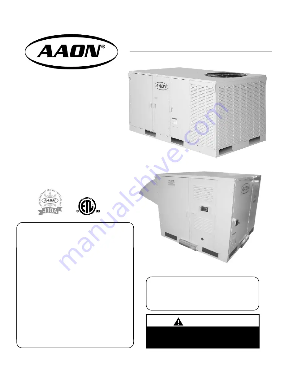
Package Units  
& Air Handlers 

R-410A Package 

Air Handler 

  R-410A DX or Chilled Water Cooling 

  Gas, Electric or Hot Water Heat 

  Bottom or Side Discharge 

Summary of Contents for HB Series

Page 1: ...LIANCE DO NOT USE ANY PHONE IN YOUR BUILDING IMMEDIATELY CALL YOUR GAS SUPPLIER FROM A NEIGHBOR S PHONE FOLLOW THE GAS SUPPLIER S INSTRUCTIONS IF YOU CANNOT REACH YOUR GAS SUPPLIER CALL THE FIRE DEPARTMENT If the information in this manual is not followed exactly a fire or explosion may result causing property damage personal injury or loss of life WARNING Package Units Air Handlers R 410A Package...

Page 2: ...eating and Cooling Systems Service Installation Clearances Setting the Unit Electrical Standard Control Board Optional Control Board Optional Control Board Owner should pay particular attention to the words NOTE CAUTION and WARNING NOTES are intended to clarify or make the installation easier CAUTIONS are given to prevent equipment damage WARNINGS are given to alert owner that personal injury and ...

Page 3: ...tion and discharge pressure gauges Any alteration should only be made at the unit power connection WARNING This equipment uses R 410A only and operates at higher pressures than standard R 22 systems Do not use R 22 service equipment or tools on R 410A systems Improper use or service may result in injuries from parts under high pressure WARNING RISK OF ELECTRICAL SHOCK Before attempting to perform ...

Page 4: ...he back Table 4 1 Package Unit Dimensions Model Width Length Height 002 005 42 25 74 25 93 25 38 If present the outside air hood will increase the overall installed unit length by 19 for a total length of 93 25 Figure 4a Package Unit Orientation Compressor Compartment Condenser Section Heating Section Evaporator Section Return Outside Air Economizer Section Top Lifting Lugs on Each Corner Filter S...

Page 5: ...n is located on the back Figure 5a Air Handler Non Compressorized Unit Orientation Controls Section Power Disconnect Switch Top Lifting Lugs on Each Corner Return Outside Air Economizer Section Filter Section Heating Section Coil Section Forklift Openings Table 5 1 AHU Dimensions Model Width Length Height 002 005 42 25 44 75 63 75 38 If present the outside air hood will increase the overall instal...

Page 6: ...g Single Stage Dual Stage w 2 step compressor Single Serpentine Chilled Water Half Serpentine Chilled Water 0 1 2 M N No Cooling Non comp w Std DX Coil Non comp w Std DX Coil w RA Bypass Air Cooled Cond w Std DX Coil Air Cooled Cond w Std DX Coil w RA Bypass Chilled Water 4 Row Coil Chilled Water 4 Row Coil w RA Bypass Chilled Water 3 Row Coil w 1 Row Preheat Chilled Water 3 Row Coil w RA Bypass 1...

Page 7: ...coil to prevent undue stress from weakening connections over time Allow adequate flexibility for thermal expansion of the piping Use proper glycol solutions or brines to help prevent coil freezing Consult the designer or project engineer if you have concerns about lower than normal entering air temperatures typically air temperatures below 40 F that could cause coils to freeze Gas or Electric Heat...

Page 8: ...etting With these settings the system is shut down except for the 24 volt control system power and the compressor crankcase heater approx 60W Night and Vacancy Operation To reduce the operation time during low load periods it is recommended that the temperature setting be increased by 5 F during non occupied periods of the cooling season in commercial buildings such as nights and weekends Decrease...

Page 9: ...e insulated with closed cell polyurethane foam which has twice the R value of fiberglass insulation All cabinet walls and roof use double wall G90 galvanized steel The solid core foam interior provides a rigid impact resistant surface All panels have a thermal break with no metal to metal contact from outside to inside Thermal Break Foam Core Double Wall Figure 9b High Performance Composite Panel ...

Page 10: ...g in place Secure all loose shipped items 5 Installation General DX models of this unit use R 410A refrigerant only and should not be used with any other refrigerant HB package units are for outdoor installation only Codes Ordinances System should be sized in accordance with National Warm Air Heating and Air Conditioning Association Literature or the Guide of American Society of Heating Refrigerat...

Page 11: ...efrigeration systems are factory assembled charged with refrigerant tested and operated These systems include liquid line filter driers expansion valves and fully hermetic scroll compressors Compressors are equipped with a positive pressure forced lubrication system The air cooled condenser coil is constructed of copper tubes and mechanically bonded aluminum fins and air is pulled through by a pro...

Page 12: ...eft Front Back Figure 12a Service Clearance Minimums Airflow to and from the condensing unit must not be restricted Obstruction to airflow will result in decreased performance and efficiency The installation position must provide at least 20 inches of condenser clearance for proper airflow into the condenser coil When the unit s condenser is positioned adjacent to another condenser 48 inches of cl...

Page 13: ...care should be taken to prevent damage to the unit It is recommended that the unit be hoisted with the outside air hood if present in the shipped position However the unit may be hoisted with the outside air hood in an open position Before lifting unit be sure that all shipping material is removed Secure hooks and cables at all lifting points lugs provided on the unit Prior to setting the unit ont...

Page 14: ...s are provided for connection to the wall mounted thermostat of the customer s selection or as furnished by AAON Confirm the optional features that were specified and purchased with the HB conditioner This will allow proper selection of the number of control options listed below that may need additional wiring Install gas fired units so that the flue discharge vent is located a minimum of 120 from...

Page 15: ...e conduit from power wiring Connect control wiring to low voltage terminal block Optional Control Board Compressor and Control Compartment Red yellow and green LEDs for fault mode and power indicators Standard Control Board has low voltage terminals for R G Y1 Y2 W1 W2 W3 GND GND is the ground or C side of the low voltage power supply transformer Standard Control Board Optional Control Board has e...

Page 16: ...ion of the equipment The HB control board has approximately a 1 2 amp current flow through the thermostat Follow the thermostat manufacturer s instructions to set the heat anticipator Length of Wire Run T stat Load Amps 50 Ft 100 Ft 150 Ft HB Less than 1 0 18ga 18ga 16ga Single Stage Heating Cooling The R G Y W terminals on a single stage thermostat should be connected to the similarly labeled ter...

Page 17: ... supply air temperature back to the unit control board Factory Installed When factory installed the control board will use the outdoor air sensor and the cooling signal from the thermostat to provide a first stage of cooling using the outside air when possible before starting the compressor and mechanical cooling cycle The thermostat wiring to the control board with single or multi stages should b...

Page 18: ...18 Figure 18a External Control Inputs to Control Board ...

Page 19: ...e terminal as shown in Figure 18a The reset range is determined by the setting configured on the DIP switch labeled RESET LIMIT The controller will reset the supply air temperature setpoint from the value set on the SETPOINT DIP switch to the value set on the RESET LIMIT DIP switch as the Reset Input MHGRV RSET signal is increased from 0 Volts to 10 Volts Example We want the Discharge Air Temperat...

Page 20: ...20 Figure 20a Reheated Supply Air Temperature ...

Page 21: ...In compliance with the ANSI Z21 80 Line Regulator Standard installations with gas supply pressures in excess of 2 PSI and less than 5 PSI require a tested and approved over pressure protection device OPD for use with the regulator as a means to limit the downstream pressure to 2 PSI maximum in the event of regulator failure For proper heating operation pressure to the regulator MUST NOT BE greater...

Page 22: ...idewall into heating cabinet Remember to seal around all exterior cabinet penetrations at utility entries Gas valve installed at factory Piping to gas valve inlet must be completed in field Valve Inlet Bottom or Side Utility Entry Options Sidewall Entry Piping assembly ready to connect to field supplied gas line Gas Valve Figure 22a Gas Piping ...

Page 23: ...nnel 6 Start Up General ONLY QUALIFIED AUTHORIZED PERSONNEL SHOULD POWER ON OR START UP THIS EQUIPMENT The use of common sense and good practice in the installation and start up of equipment will prevent many potential problems with the system in the future Before starting up the equipment building construction should be complete and start up personnel should Have a working knowledge of general HV...

Page 24: ... with an economizer after testing of cooling circuits is complete turn cooling circuits off and leave blower running 10 Call for the economizer circuit to operate 11 Check for economizer blades to open fully with no binding Gas Heating 1 Ensure that gas lines have been purged of air wait 5 minutes after purging to allow gas to clear before continuing with startup 2 Turn the unit power on 3 Turn th...

Page 25: ...ational sequences Air Balancing High performance systems commonly have complex air distribution and fan systems Unqualified personnel should not attempt to adjust fan operation or air circulation as all systems have unique operating characteristics Professional air balance specialists should be employed to establish actual operating conditions and to configure the air delivery system for optimal p...

Page 26: ...nd or a non corrosive coil cleaning solution Condenser Coil One of the most overlooked maintenance requirements is the need to keep air moving freely across air cooled condensing coils Dirty condensers like evaporators can significantly increase cooling costs during the year As a minimum clean the condenser coil at the beginning of each cooling season It is preferable to use a medium pressure wate...

Page 27: ...eating safety devices used as part of the Heat Safety Monitor are MLS ALS ROS and DPS If any of these devices trip 3 times during a heating call then the heating will be locked out To restore normal operation remove the call for heating or cycle the power Chilled Water Check remote chiller operations as per the manufacturer s instructions Check coolant flow valves for correct operation and setting...

Page 28: ...oid cooling the space excessively while removing moisture a coil which accepts discharge gas from the compressor is located downstream of the evaporator The function of this coil is to heat the air that has been cooled by the evaporator to approximate room temperature A reheat valve is installed in the compressor discharge line to divert discharge gas to the reheat coil when the humidistat calls f...

Page 29: ...29 ...

Page 30: ...30 ...

Page 31: ...69 6 90 273 5 120 416 9 150 611 9 31 98 8 61 172 5 91 277 6 121 422 5 32 100 9 62 175 4 92 281 7 122 428 2 33 102 9 63 178 4 93 285 9 123 433 9 34 105 0 64 181 5 94 290 1 124 439 6 35 107 1 65 184 5 95 294 4 125 445 4 36 109 2 66 187 6 96 298 7 126 451 3 37 111 4 67 190 7 97 303 0 127 457 3 38 113 6 68 193 9 98 307 5 128 463 2 39 115 8 69 197 1 99 311 9 129 469 3 40 118 1 70 200 4 100 316 4 130 47...

Page 32: ...nt of AAON to provide accurate and current specification information However in the interest of product improvement AAON Inc reserves the right to change pricing specifications and or design of its products without notice obligation or liability AAON is a registered trademark of AAON Inc Effective June 2006 Supercedes December 2005 R33010 06 06 ...

Reviews: