


74
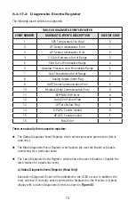
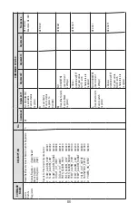
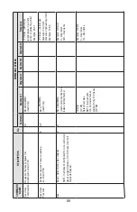
TABLE XX: DIAGNOSTIC EVENTS REGISTER
EVENT NUMBER
DIAGNOSTIC EVENTS DESCRIPTION
OLED BIT CODE
1
CPU Temperature Too High
0
2
DP Sensor Initialization Error
1
3
AP Sensor Initialization Error
2
4
2.5 Vdc Reference Out of Range
3
5
Flow Out of Permissible Range
4
6
Absolute Pressure over Permissible Range
5
7
Gas Temperature Out of Range
6
8
Analog Output Alarm Flag
7
9
UART Serial Communication Error
8
10
Modbus Serial Communication Error
9
11
EEPROM R/W Error
A
12
Auto Zero Failure Flag
B
13
AP Tare Failure Flag
C
14
DP ADC Counts Invalid
D
15
AP ADC Counts Invalid
E
16
Fatal Error
F
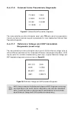
6.4.17.2 Diagnostic Events Register
The following alarm events are supported:
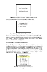
There are actually three separate registers:
The Status Diagnostic Event Register, which holds each active alarm event (this is
read
only).
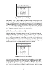
The Mask Diagnostic Event Register, which allows the user the Enable or Disable
monitoring for a particular event.
The Latch Diagnostic Event Register, which allows the user to Enable or Disable the
latch feature for a particular event.
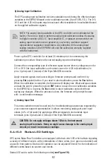
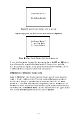
a) Status Diagnostic Event Register (Read Only)
Each active Diagnostic Event will be indicated on the OLED screen. In addition, the
total number of currently active events will be displayed on the fi rst line. A typical
display with no active Diagnostic Events is shown in
Figure 48:
Summary of Contents for DPC
Page 6: ...2...
Page 120: ...116 APPENDIX I COMPONENT DIAGRAM Top Component Side...
Page 121: ...117 Bottom Component Side...


