background image

14

14

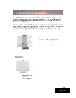
The MyM-3T can be installed either as a stand alone unit directly on the wall or by the use of a 
dedicated MyM Security Wall Mount (part number 702800.10). The MyM Security Wall Mount 
secures both the MyM and CAM-modules with a locking function to avoid loss of CAM’s and 
smart cards in public places.

Before connecting power to the MyM-3T, make sure that all other connections have been made. A 
coaxial cable of good quality with an F-connector should be connected  to the Antenna  input and 
another one from the RF output to the SMATV network. 
Connect the power supply and make all necessary settings as described in section 4 and 5. 

English

Installation in MyM Security Wall Mount.

MyM Security Wall 
Mount kit
Art no: 702800.10

Accessories

6 Installation and configuration

Summary of Contents for MyM-3TMicro Master

Page 1: ...1 1 MyM 3TMicro Master Installation Guide design for TV English...

Page 2: ...settings 5 Menus and settings 5 1 Overview menu 5 2 Input settings 5 3 Output settings 5 4 Service management 5 5 CI menu 5 6 System options 6 Installation and Configuration examples 7 Technical speci...

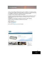
Page 3: ...es DVB S and DVB S2 transmissions The MyM 3T unit is delivered with hardware and software that supports DVB S S2 reception MPEG2 MPEG4 decoding DSB RF modulation with NICAM or A2 audio IP control and...

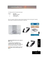
Page 4: ...ice see page 3 for contact info English Important information about power supply to MyM 3T unit To avoid problems with theMyM 3T its is important to use the supplied power supply Operation with other...

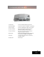
Page 5: ...a Common Interface module into this slot Supports decryption for Channel 1 and 2 5 Common Interface 2 Insert a Common Interface module into this slot Supports decryption for Channel 3 6 Ethernet port...

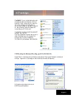
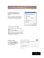
Page 6: ...the default IP address 192 168 0 20 First time installation requires that you set a static IP address on your computer For example set your PC to IP address 192 168 0 19 and Net mask 255 255 255 0 En...

Page 7: ...ng your PC to the MyM 3T Connect the MyM 3T to the supplied DC power supply See section 6 for installation Next connect your PC to the MyM 3T with a network cable Start your web browser Internet Explo...

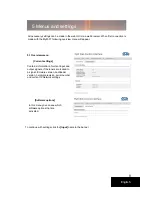
Page 8: ...rdware revision serial number and current IP Network settings All necessary settings can be made in the web GUI via a web browser When first connection is made with the MyM 3T following overview menu...

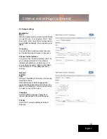
Page 9: ...ngs As the MyM 3T contains 2 separate tuners start by selecting either Tuner 1 or Tuner 2 Bandwidth can be selected between 6 7 or 8 MHz Write the center frequency of the wanted Mux and press Set 5 Me...

Page 10: ...rsonal preference The Channel Indicator will enable you to detect on a TV screen which programs that are transmitted from the MyM 3T Press Set after each entering National Subtitle Type Set type of su...

Page 11: ...Select here if loopthrough for input antenna signal shall be On or Off 5 Menus and settings continued 5 3 Output settings continued Auto conversion Converts subtitling to fit actual picture aspect rat...

Page 12: ...ed SID Service ID number as received NOTE To detect whether a Common Interface module and smart card actually decrypts the programs is only possible by watching the outgoing signal on a TV set tuned t...

Page 13: ...ves statistics of uptime and possible re starts The log can be cleared in order to have a clean sheet after installation IP settings This section shows current IP address Netmask and Gateway settings...

Page 14: ...s in public places Before connecting power to the MyM 3T make sure that all other connections have been made A coaxial cable of good quality with an F connector should be connected to the Antenna inpu...

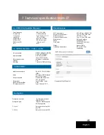
Page 15: ...t level Typ 80 dB V fixed Built in aerial amplifier 5 dB RF output connector Type F female 75 Input frequency 950 2150 MHz Symbol rate 1 45 Msymbols s Connectors Type F female 75 Input level 65 to 25...

Page 16: ...16 16 The document for Declaration of Conformity is available for download from www a2b se Further information at www a2b se English 8 Declaration of Conformity...

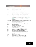
Page 17: ...little or no manual configuration Common Interface Connector for a PCMCIA module used for decrypting encrypted TV programs Modules should comply with the DVB CI standard SD Standard definition TV 576...

Page 18: ...18 Notes...

Page 19: ...19 Notes...

Page 20: ...ics AB S dra All n 23 25 591 37 Motala P O Box 14 591 21 Motala SWEDEN Phone 46 141 229100 Fax 46 141 229101 E mail market a2b se To view our full line of Professional Products visit our Web site www...

Reviews: