A.O. Smith HIGH EFFICIENCY ATMOSPHERIC VENTGAS WATER... Use & Care Manual Download Page 24

24

Powered Anode Operation

To protect the glass-lined water tank from corrosion 
through electrolysis, this water heater is equipped with a 
non sacrificial powered anode rod. The powered anode 
rod is non sacrificial and should not need to be replaced 
unless damaged.
If the powered anode rod has been damaged then the 
powered anode rod should be removed and replaced 
from the water heater tank. IMPORTANT: If the damaged 
powered anode rod has not been replaced but has been 
remove permanently, this will void any warranties. 

FIGURE 22.

NOTE: Whether re-installing or replacing the powered 
anode rod, check for any leaks and immediately correct if 
found.

In replacing the powered anode:
1.  Turn off electrical supply and gas supply to the water 

heater.

2.  Shut off the water supply and open a nearby hot water 

faucet to depressurize the water tank.

3.  Drain approximately 5 gallons of water from tank 

(Refer to the “Draining and Flushing” section for proper 
procedures). Close drain valve.

4.  Remove the wiring connection on the top of the 

powered anode and remove the old powered anode 
rod (Figure 22).

5. Use 

Teflon

®

 tape or approved pipe sealant on threads 

and install new anode rod.

6.  Turn on water supply and open nearby hot water faucet 

to purge air from water system. Check for any leaks 
and immediately correct any if found.

7.  Turn on electrical and gas supplies. Restart the water 

heater as directed under the “Operating Your Water 
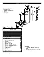
Heater.” See the “Repair Parts Illustration” section for 
anode rod location.

TEFLON

® 

is a registered trademark of E.I. Du Pont De Nemours and Company

Draining and Flushing

It is recommended that the tank be drained and flushed 

every 6 months to remove sediment which may build up 

during operation. The water heater should be drained if 

being shut down during freezing temperatures. To drain the 

tank, perform the following steps:
1.  Turn off the gas to the water heater at the manual gas 

shut-off valve and turn off the electrical power to the 

gas control/thermostat valve.

2.  Open a nearby hot water faucet until the water is not 

longer hot.

3.  Close the cold water inlet valve.
4.  Connect a hose to the drain valve and terminate it to 

an adequate drain or external to the building.

5.  Open the water heater drain valve and allow all the 

water to drain from the tank. Flush the tank with water 

as needed to remove sediment.

6.  Close the drain valve, refill the tank, and restart the 

heater as directed in this manual.

If the water heater is going to be shut down for an 

extended period, the drain valve should be left open.
IMPORTANT: Condensation may occur when refilling the 

tank and should not be confused with a tank leak.

Routine Preventive Maintenance

At least annually, a visual inspection should be made of 

the venting and air supply system, piping systems, and 

main burner. Check the water heater for the following:
• 

Obstructions, damage, or deterioration in the venting 

system. Make sure the ventilation and combustion air 

supplies are not obstructed. 

• 

Clean any dust or debris from the louvers of the air 

intake chamber.

• 

Soot and/or carbon on the main burner. Contact a 

qualified technician.

• 

Leaking or damaged water and gas piping.

• 

Presence of flammable or corrosive materials in the 

installation area.

• 

Presence of combustible materials near the water 

heater.

• 

After servicing this water heater, check to make sure 

it is working properly. (See “Operating Your Water 

Heater” section of this manual.)

IMPORTANT: If you lack the necessary skills required to 

properly perform this visual inspection, you should not 

proceed, but get help from a qualified technician.

Powered

Anode

Rod

Powered Anode System

To ensure a long, trouble-free

operating life, this water 

heater is equipped with a 

powered anode system.

The powered anode rod is of 

a permanent design and does 

not need replacing unless 

damaged.

Summary of Contents for HIGH EFFICIENCY ATMOSPHERIC VENTGAS WATER...

Page 1: ...pplier s instructions If you cannot reach your gas supplier call the fire department Installation and service must be performed by a qualified installer service agency or the gas supplier WARNING If t...

Page 2: ...lief Valve 16 17 T P Relief Valve and Pipe Installation 17 Combination Space Heating Potable Water System 17 18 Solar Installation 18 Electrical Connections and Wiring Diagram 18 Important Information...

Page 3: ...ty equivalent to a licensed tradesman in the fields of plumbing air supply venting and gas supply including a thorough understanding of the requirements of the National Fuel Gas Code as it relates to...

Page 4: ...s are available Breathing carbon monoxide can cause brain damage or death Always read and understand instruction manual Fire or Explosion Hazard Do not store or use gasoline or other flammable vapors...

Page 5: ...CODES IMPORTANT WHEN BRUSHING ON AN APPROVED NONCORROSIVE LEAK DETECTION SOLUTION DO NOT SPLASH SOLUTION ONTO ELECTRICAL CON NECTIONS SEE PAGE 27 M N A L B P D E Q F G DISCHARGE PIPE DO NOT CAP OR PLU...

Page 6: ...future users of this water heater will need it for future reference Service to the FVIR System should only be performed by a qualified technician Examples of a qualified technician include licensed pl...

Page 7: ...ignition sources have been extinguished Fire or Explosion Hazard WARNING Read instruction manual before installing using or servicing water heater Improper use may result in fire or explosion Maintain...

Page 8: ...ply wholesalers and retailers and detect and react to leakage in various ways Sensors mounted in the metal drain pan that trigger an alarm or turn off the incoming water to the water heater when water...

Page 9: ...PPLY WARNING Use a new CSA approved gas supply line Install a shut off valve Do not connect a natural gas water heater to an L P gas supply Do not connect an L P gas water heater to a natural gas supp...

Page 10: ...these instructions can result in death explosion or carbon monoxide poisoning Explosion Hazard Gas Pipe Capacity Table WARNING Explosion Hazard Gas leaks can not always be detected by smell Gas suppl...

Page 11: ...y a qualified technician using the installation instructions Examples of a qualified technican include gas technicians authorized gas company personel and authorized service persons Failure to so do c...

Page 12: ...for ventilation and combustion air supply openings consideration must be given to the blocking effect of protection louvers grilles and screens These devices can reduce airflow which in turn may requi...

Page 13: ...ing the manufacturer s instructions and local codes rules or regulations IMPORTANT If you lack the necessary skills required to properly install this venting system you should not proceed but get help...

Page 14: ...prior to any elbow in the vent system IMPORTANT Existing vent systems must be inspected for obstructions corrosion and proper installation Chimney Connection IMPORTANT Before connecting a vent to a c...

Page 15: ...he water heater and be easily accessible Know the location of this valve and how to shut off the water to the heater 6 A temperature and pressure relief valve must be installed in the opening marked T...

Page 16: ...or other chemicals must not be used Chemicals that may contaminate the potable water supply must not be added to the piping system Closed System Thermal Expansion As water is heated it expands thermal...

Page 17: ...ed into the T P valve discharge opening per the instructions manual 4 Locate the hot water outlet cold water inlet pipes to the water heater 5 Locate the slit running the length of a section of pipe i...

Page 18: ...tions for leaks Open the nearest hot water faucet and let it run for three 3 minutes to purge the water lines of air and sediment and to ensure complete filling of the tank The Electrical power may th...

Page 19: ...se review the following checklist and make any required installation upgrades or changes Questions Contact Residential Technical Assistance by referencing the phone number on the front of the Installa...

Page 20: ...performed 3 Set the ON OFF switch on the gas control to the OFF postition 2 6 This appliance is equipped with a device which automatically lights the burner DO NOT TRY TO LIGHT THE BURNER BY HAND This...

Page 21: ...code 8 page 31 FIGURE 17 SEQUENCE OF OPERATION System will verify pressure switch operation and start a 5 second pre purge then air intake fan will turn off Ignitor will start a 12 second warm up peri...

Page 22: ...hermostat see Figures 20 and 21 Using the lowest hot water temperature that meets your needs will also provide the most energy efficient operation of the water heater Never allow small children to use...

Page 23: ...the water heater cannot be used until the gas control valve thermostat is replaced by a qualified technician Contact your local dealer for service information losses and may satisfy your normal hot wa...

Page 24: ...s To drain the tank perform the following steps 1 Turn off the gas to the water heater at the manual gas shut off valve and turn off the electrical power to the gas control thermostat valve 2 Open a n...

Page 25: ...Manifold Burner Assembly 1 Turn off the gas supply to the water heater at the manual gas shut off valve This valve is typically located beside the water heater Note the position of the shut off valve...

Page 26: ...dirt it may be necessary to check the air intake chamber screen more frequently 2 Use a vacuum cleaner with a hose attachment to remove any dust or debris that may have accumulated on the screen FIGU...

Page 27: ...eater Refer to the section of Draining and Flushing section and follow the procedure 5 Disconnect the the flame sense hot surface igniter wire power supply transformer pressure switch fan and display...

Page 28: ...PERATURE REGULATION section BURNER FLAME YELLOW LAZY 1 Dirt in burner ports 2 Combustion air path restricted 3 Not enough dilution air for proper com bustion 4 Main burner line clogged 5 Obstruction i...

Page 29: ...MATION SOOTING 1 Insufficient secondary air 2 Low gas pressure 3 Water heater flue or vent system blocked 4 Thermostat not functioning properly 5 Heater installed in a confined area 6 Burner flame yel...

Page 30: ...ure supply and manifold gas pressures are within requirements in the installation manual Manifold gas pressure is non adjustable if pressure is off by more than 0 3 W C 75 Pa replace the lower control...

Page 31: ...power for 10 seconds and then back on If this error code will not clear and the ignitor resistance is within specifications replace the lower control 9 FV SENSE Flashing Flammable Vapor Sensor has det...

Page 32: ...control must be replaced 15 All Segments Flashing The self diagnostic check has detected one or both of the temperature adjustment buttons are stuck 1 Press and release each of the temperature adjustm...

Page 33: ...DURING TRIAL FOR IGNITION IGNITOR TURNS OFF YES NO IS FLAME SENSE LOST IS REQUEST FOR HEAT SATISFIED GAS VALVE OFF COMBUSTION FAN OFF AFTER POST PURGE DELAY GAS VALVE CLOSES LESS THAN 3 TRIES FOR IGN...

Page 34: ...w Retainer Clip 16 Manifold Door Gasket 17 Viewport Assembly 18 FV Sensor 19 Outer Door 20 Electrical Transformer 21 Pressure Switch REPAIR PARTS ILLUSTRATION LEGEND Special anode rod see Anode Rod Wa...

Page 35: ...assembly which contains the manifold tube gasket manifold door manifold component block with retainer clip and flame sense hot surface igniter assembly Natural Gas Item 15 Contains manifold component...

Page 36: ...36 NOTES...

Page 37: ...37 NOTES...

Page 38: ...38 NOTES...

Page 39: ...niques for residential water heaters bearing a rating plate which has not been altered defaced or removed except as required by the warrantor used in an open system or in a closed system with a proper...

Page 40: ...M DOES NOT CONSTITUTE PROOF OF PURCHASE OR PROOF OF INSTALLATION DISCLAIMERS NO EXPRESSED WARRANTY HAS BEEN OR WILL BE MADE ON BEHALF OF THE WARRANTOR WITH RESPECT TO THE MERCHANTABILITY OF THE HEATER...

Reviews: