3rd Eye MobileVision AWT07MLED, User Manual
Get the most out of your 3rd Eye MobileVision AWT07MLED with our comprehensive User Manual. Available for free download at manualshive.com, this manual is your go-to resource for understanding every feature and optimizing your mobile visibility experience. Ensure you have all the information you need to master your device.
Share
Download


Reviews:
No comments
Related manuals for MobileVision AWT07MLED
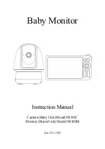
B180C
Brand: GardePro Pages: 49

Forerunner 305 - Running GPS Receiver
Brand: Garmin Pages: 2
Aurora Vision
Brand: DCI Pages: 8

NLM155A1
Brand: NewCommWorld Pages: 19

BP5S
Brand: iHealth Pages: 210

BRX 5000
Brand: brennenstuhl Pages: 66

NVM-800MC
Brand: NA-DE Pages: 4

SM-ZVM-134
Brand: Zenith Data Systems Pages: 43

BY 33
Brand: Beurer Pages: 29

F17AH-D
Brand: GVision Pages: 15

E90-3
Brand: ViewSonic Pages: 18

XG2703-GS
Brand: ViewSonic Pages: 25

FW619AHT
Brand: Feelworld Pages: 13

SYK-1018
Brand: Symphony Pages: 7

GW22059
Brand: GoWISE USA Pages: 18

SOLO 900
Brand: Sportline Pages: 16

Zeus3S
Brand: B&G Pages: 30

HDPDP4200
Brand: Sansui Pages: 40


