User manual
12
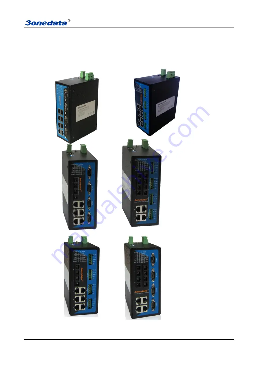
Chapter 3 Appearance and Dimension
3.1 Appearance
IES618-4D series
Page 1: ...User manual 1 IES618 4D series Managed Industrial Ethernet switch User manual Version 1 0 0 July 2013 www 3onedata com cn ...
Page 2: ... to their respective manufacturers Agreement As the product version upgrades or other reasons this document is subject to change without notice Unless other agreement this document only as a guide to use All statement information and suggestion in this document without warranty of any kind either expressed or implied Revision History Version No Date Reason V1 0 0 2013 7 Creating Documents Notes In...
Page 3: ...16 5 3 INTRODUCTUIN CONFIGURE INTERFACE 17 5 3 1 Main menu 17 5 3 2 System status 18 5 3 2 1 Deivce information 18 5 3 2 2 Port information 19 5 4 SERIAL DEVICE SERVER 19 5 4 1 Configure serial port parameter 19 5 4 2 Configure working mode 21 5 4 3 Serial port information 24 5 5 Port configuration 24 5 5 1 Port settings 24 5 5 2 Bandwidth management 26 5 6 L2 FEATURES 28 5 6 1 VLAN 28 5 6 1 1 Bas...
Page 4: ...2 BASIC SETTINGS 50 5 12 1 Device address 50 5 12 2 System identification 51 5 12 3 System File Upgrade 51 5 12 4 System logout 53 CHAPTER 6 OTHER FUNCTION CONFIGURE 54 6 1 DIP SWITCH 54 6 1 1 Factory default 54 APPENDIX 1 GLOSSARY TABLE 55 APPENDIX 2 DEFAULT FACTORY 56 APPENDIX 3 TREATMENT OF COMMON PROBLEM 57 APPENDIX 4 EXAMPLE OF CONFIGURATION 错误 未定义书签 ...
Page 5: ...low power consumption design IP40 corrugate high strength iron shell the performance is more steadily It accorded with CE FCC standard and Industrial 4 class DIN rail installation and wide operating temperature 40 75C it can satisfied some kinds of industrial environment it can provide reliable and quickly solution for your Ethernet device SWRingTM is designed as rapid redundancy network arithmeti...
Page 6: ... MAC address table Support power reverse connection protection Support redundant power supply delay alarm output heat radiation naturally and LED indicator front and back IP40 protection grade Industrial grade 4 design 40 75 work temperature 5 95 relative humidity Power requirements 24VDC 12 48VDC DIN rail hanging and panel mounting ...
Page 7: ...t panel Back panel Top panel Bottom panel 1 PWR1 PWR2 power input 2 Ground screw 3 Relay output terminal block 4 DIP switch 5 DIN Rail mounts 6 CONSOLE port 7 RS 232 serial port 8 10Base T 100Base TX port 9 LED indicator IES618 4DI RS 485 P 12 48VDC Front panel Back panel Top panel Bottom panel ...
Page 8: ...85 422 serial port 8 10Base T 100Base TX port 9 LED indicator IES618 2F 4D RS 232 P 12 48VDC Front panel Back panel Top panel Bottom panel 1 PWR1 PWR2 power input 2 Ground screw 3 Relay output terminal block 4 CONSOLE port 5 DIP switch 6 DIN Rail mounts 7 10Base T 100Base TX port 8 RS 232 serial port 9 100Base FX port 10 LED indicator ...
Page 9: ...crew 3 Relay output terminal block 4 CONSOLE port 5 DIP switch 6 DIN Rail mounts 7 10Base T 100Base TX port 8 RS 485 422 serial port 9 100Base FX port 10 LED indicator IES618 4F 4D RS 232 P 12 48VDC Front panel Back panel Top panel Bottom panel 1 PWR1 PWR2 power input 2 Ground screw 3 Relay output terminal block 4 CONSOLE port ...
Page 10: ...se TX port 8 RS 485 422 serial port 9 100Base FX port 10 LED indicator 2 2 Power supply input IIES618 4D series top panel provided 4 bit power supply input terminal block support DC input DC power supply input supported redundancy function provided PWR1 and PWR2 power input can use for single and can connect 2 separately power supply system use 1 pair terminal block connect the device at the same ...
Page 11: ...y 3 is for upgrade Please power off and power on when you change the status of DIP switch 2 5 Communication port 10Base T 100Base TX Ethernet port 10Base T 100Base TX Ethernet port is located on front panel and the type is RJ45 The pinout of RJ45 port connects to UTP or STP The distance is not more than 100m 100Mbps Ethernet connector takes 120Ωof UTP 5 10Mbps Ethernet connector takes 120Ωof UTP 3...
Page 12: ... port must be used in pair TX transmitting port connects remote switch s RX receive port RX receiving port connect remote switch s TX transmitting port Suppose If you make your own cable we advise to label the two sides of the cable with the same letter A to A and B to B shown as below or A1 to A2 and B1 to B2 2 6 Serial port connection RS 232 Serial port PIN RS 232 1 DCD 2 RxD 3 TxD 4 DTR 5 GND 6...
Page 13: ... RS 485 422 2 7 LED Indicator LED Indicator Description PWR1 ON P1 connection regularly OFF P1 Power supply have no connection or unwonted PWR2 ON P2 connection regularly OFF P2 Power supply have no connection or unwonted Run ON OFF Device unwonted Flashing Device working steadily Link ACT ON Established effective network connection ...
Page 14: ...n In order to use in industrial environments expediently IES618 4D adopts 35mm DIN Rail installation the installation steps as follows 1 Examine the DIN Rail attachment 2 Examine DIN Rail is firm or not and the position is suitable or not 3 Insert the top of the DIN Rail into the slot just below the stiff metal spring 4 The DIN Rail attachment unit will snap into place as shown below Wiring Requir...
Page 15: ...y are in the same groove road When cable is too long it cannot hold down other cable but structure in the middle of alignment rack 8 Pigtail cannot be tied and swerved as less as possible Swerving radius cannot be too small small swerving causes terrible loss of link Its banding should be moderate not too tight and should be separated from other cables 9 It should have corresponding simple signal ...
Page 16: ...User manual 12 Chapter 3 Appearance and Dimension 3 1 Appearance IES618 4D series ...
Page 17: ...User manual 13 3 2 Dimension ...
Page 18: ...ories by your first using Please inform us or our distributor if your equipments have been damaged or lost any accessories we will try our best to satisfy you Description Quantity 3onedata Industrial Ethernet switch 1 User manual 1 CD 1 Warranty card 1 Product Qualified Card 1 ...
Page 19: ...ssfully Method 2 Modify IES7110 2GS series s IP address through Blue_eyes manager software Install Blue_eyes manager software on the PC Enter into Blue_eyes management interface click Search to search the device After searching the device move mouse to the device click right key modify the device s IP address Please make sure the device and PC in the same Local Area Network This configuration exam...
Page 20: ...and password log on to the Web Server it will recommend to modify the user name and password Please contact our customer service center if you have more questions 5 2 Login WebServer Please type in the default IP of switch on the browsers s address bar and then will pop up a window by clicking the enter key which shows you have to enter your user name and password The default username and password...
Page 21: ...ersion IP address etc Serial device servers Serial configuration Serial parameter and Working mode configuration Serial information Display incorrect data statistics and connection information that send by serial port Port Configuration Port settings Display and configure information of each port such as connection status configuration modes flow status etc Bandwidth management Set the maximum rat...
Page 22: ...ed in the Web interface If user doesn t operate the Web interface for a long time The system will be canceled this login but configuration change made in this login will be saved in Web configuration interface If the user wants to do any operating on Web configuration interface again the system will remind user and returns to the login dialog box Users need to log in again if operating is needed T...
Page 23: ...s that the port is in a connected state LOS Indicates that the port is not connected FULL Indicates that the port State is full duplex HALF Indicates that the port State is half duplex if the ports are not connected the port status is HALF Figure 5 3 4 5 4 Serial device server Server configuration includes the serial port configuration and mode of operation of the configuration parameters 5 4 1 Co...
Page 24: ...ud rate It is a parameter to check the communication speed It shows to transfer how many bits in 1 second For example 300 baud rate means have 300 bits transferred in 1 second Parity Parity bits It is a simple method to checkout fault in serial communication have 4 types Even Odd Mark Space Data Bits It is a parameter to check the actual data bits in communication When PC send a Packet actual data...
Page 25: ...sconnect Timeout 0 65535 s Default is 300 RealCom Open Close Default is Close Sessions Each serial port of serial device servers can support 1 4 sessions It means serial port of serial device server send the received data to Ethernet through socket More than one of the sessions means serial port of serial device server sends the received data to Ethernet through more than one socket sessions enabl...
Page 26: ...erface of TCP Client Mode Session 1 is setting to local address available for router 192 168 2 168 the Destination Port connected to serial port is host computer 192 168 2 168 31000 port Connection mode is Immediately Disconnect Timeout time is 300 seconds please pay attention to pure TCP Client TCP Server UDP or TCPAuto mode Please close RealCom Session 3 is setting to Internet address available ...
Page 27: ...n and close function in RealCom figure 5 4 3 When device open the RealCOM function can cooperate with VSP Management Software create virtual COM port to communication now device s work mode is server the virtual COM port is client how to create the Virtual COM port please the VSP Management Software user manual Figure 5 4 3 Advanced mode 1 TCP server Under this mode series is server IES618 4D can ...
Page 28: ...formation It main function of serial port information Display incorrect data statistics and connection information that send by serial port Figure as 5 4 6 Figure 5 4 6 5 5 Port configuration 5 5 1 Port settings The port configuration interface mainly include port type Electric port or optical port setup speed mode and duplex mode flow control Only when the port is enabled for the port speed duple...
Page 29: ...f any port disable The default is Enable Flow Control Whether selecting flow control to the port Only can selecting flow control when the port enable The default is off Port setting interface as shown in Figure 5 5 1 Figure 5 5 1 This feature is consistent with the port status of the port information for example set port 1 and port 2 is for the hundreds of megabytes rate half double work use netwo...
Page 30: ...data s egress and ingress bandwidth to save the network sources Click port setting bandwidth management and enter into the following interface Egress Bandwidth Configuration stands for no limitation for the speed the others are corresponding speed As shown in following figure 5 3 3 the forcible egress rate of Port 5 is 8Mbps Only need to select 8Mbps in egress rate setting of Port 5 The bandwidth ...
Page 31: ...nly The ingress rate is related to CoS priority Priority Queue is based on QoS setting the same as QoS assorted setting includes checking CoS priority or ingress rate will be based on default CoS priority includes 4 queues Low Normal Medium High Operation method 1 Choice 2 port at first for example open the COS priority of port 4 and port 5 please according to 6 5 part 2 Then set port 4 s CoS is H...
Page 32: ...LAN It just changed the inside exchange rule cannot achieve across switch 1 Choice VLAN Group like as 3 means VLAN1 2 Choice VLAN member like as choice port 2 and port 3 3 Choice Add Edit 4 Choice Apply then port 2 and port 3 were divided in VLAN3 they are in same VLAN can transfer and receive data for each other 5 6 1 2 Based on IEEE 802 1Q VLAN IES618 4D supports based on 802 1Q VLAN It deals wi...
Page 33: ...e the mark when transmit Unmodify No need to modify original VLAN mark Untagged It is a normal Ethernet message Tagged Added a 4 bytes VLAN information after original MAC address and destination MAC address 3 Parameter item description Item Description PVID Port s LAN ID value range 1 4095 VID VLAN ID number value range 1 4095 Power type Include Access and Trunk Member type Unmodify Untagged Tagge...
Page 34: ...nt VLAN item setting and set up member s type of the port according to the steps for creating new VLAN 3 Click Add button select OK when reminds whether overwrite it as shown in Figure 5 6 2 Add new VLAN items into table and click Apply and reboot the device Modify VLAN finished Figure 5 6 2 6 Delete VLAN Steps of remove VLAN are as follows 1 Firstly select VLAN items which need to remove like as ...
Page 35: ...th Port 5 the port must belong to a same member of VLAN the same Port 4 can intercommunicate with Port 5 the port must belong to a same member of VLA port 3 and port 4 belongs to different VLAN figure as 5 6 5 1 Port 3 s PVID 2 Port 4 s PVID 3 Port 5 s PVID 4 port type are both Access 2 Add VLAN2 VLAN3 VLAN4 the member is 3 and 5 4 and 5 3 4 and 5 Port type is Untagged Figure 5 6 5 IES7110 2GS ser...
Page 36: ...e s low byte Configuration Description MAC Address Valid multicast address a multicast MAC address is high byte low for 1 Join Port Select desired configuration port Add The configured static multicast address entries added to the list Delete Selected multicast address is a static entry in the list click Delete delete this entry Figure 5 6 6 All none multicast address did not allow adding in this ...
Page 37: ...ifferent from COS and TOS it did not have relationship with data package it had relationship with switch port s priority If the port s priority is higher the data packet will be transferred at first When open port priority must open inspect COS The example is as figure 5 6 8 open inspect port 1 2 3 4 COS divide port 1 2 3 4 in different priority COS value corresponding priority no need to set up P...
Page 38: ... information is contained in the IP packet header DiffServ architecture using the first 6 bits of IP packet header TOS Type of Service to carry the packets classified information This definition is only for the lower 6 bits one number does not exceed 63 This definition supports both IPv4 ToS field and IPv6 Traffic Class field DSCP has 64 priority values 0 63 the lowest priority 0 and the highest p...
Page 39: ...s broken relay for failure alarm will be activated Redundant organization of SwRingTM enable backup link to recover network instantly Self developed patented technology for SW Ring network can realize the intelligent redundancy for industrial Ethernet switch which can make you easily and conveniently establish redundant Ethernet and can facilitate the quick recovery of any network section of autom...
Page 40: ...gs There has 3 type SW Ring arithmetic Ring V1 Ring V2 and Ring V3 Ring V1 support single ring Ring V2 support single and coupling ring Ring V3 Single ring coupling ring chain ring and Dual_homing Method to enabled Ring V1 1 Enable Ring V1 Select Ring V1 in Settings drop down menu figure as 5 7 2 Figure 5 7 2 2 After select Ring V1 Interface as figure 5 7 3 Ring V1 just support single ring Figure ...
Page 41: ...user use it 1 Method to enable Ring V2 coupling ring The architecture of coupling ring as figure 5 7 6 Coupling ring Figure 5 7 6 Operation method 1 Select Ring V2 enable ring group 1 and 2 Hello_time can be disable if enable time of sending Hello packet could not be very fast it will influence CPU operate speed 2 Set 105 106 device s ring port as port 7 and port 8 in ring group 1 network ID 1 typ...
Page 42: ...devices port 3 and port 4 with network cable Connect 100 101 105 106 device s port 6 with network cable Figure as 5 7 6 6 Coupling ring can work according to device VLAN normally 100 101 105 and 106 device s VLAN configuration is as figure 5 7 10 Figure 5 7 10 Method to enable Ring V3 1 Enable Ring V3 Select Ring V3 in Settings drop down menu figure as 5 7 11 Figure 5 7 11 2 After select Ring V3 C...
Page 43: ... In fact Chain is to cascade several switches already set up to Ring and both sides of chain access to network Dual Homing refers to a fact that two Rings connect the same switch This type of configuration is ideal choice for centralized management of several Rings Method to enable Chain and Dual Homing is similar to that to enable Single Ring and Coupling Ring It only needs to select correspondin...
Page 44: ...type single ring Set ring port as port 1 in ring group 2 Coupling ctrl port 4 network ID 3 type coupling ring figure as 5 7 16 Figure 5 7 16 4 Set 107 108 109 device s ring port as port 1 and port 2 in ring group 1 network ID 1 type single ring Set 102 103 104 device s ring port as port 4 and port 5 in group 1 network ID 2 type single ring 5 Connect 100 104 devices port 4 and port 5 with network c...
Page 45: ...plex rings should pay attention to the ring identity whether is it consistent different single ring identification must be different 5 7 2 RSTP The first spanning tree protocol was invented in 1985 at the Digital Equipment Corporation by Radia Perlman In 1990 the IEEE published the first standard for the protocol as 802 1D based on the algorithm designed by Perlman Subsequent versions were publish...
Page 46: ...riginal STP standard Select RSTP function in rapid ring network interface as follows Figure 5 7 20 Rapid Spanning Tree of concepts Switch priority As the bridge priority the bridge priority and bridge MAC address combine bridge ID the smallest ID bridge will become the root bridge on the network Polling interval how often send BPDU packet at one time Forwarding delay the port state of switch remai...
Page 47: ...t have network ID less than itself itself is root network bridge There did not have same network ID in network Every 2 seconds the network bridge will transmit BPDU message to all appoint port If did not receive BPDU message more than 20 seconds it realized port invalid will calculate the status of network bridge again Each status exchange for each other if need to transmit need to wait 15 seconds...
Page 48: ...ort aggregation that can not be set to ring ports 5 8 Access profile 5 8 1 User name and password Enterprise usually required two different person to monitor device and manage system network The authority need to separate Monitor person was in charge of monitor work system network person was in charge of system work management The switch provided classification management Administrator authority a...
Page 49: ...t login name and password 2 Set same user mane the front settings of user name password will be available 5 9 Remote monitoring 5 9 1 SNMP management SNMP management 1 Introduction of SNMP SNMP Simple Network Management Protocol is an internet standard protocol for managing devices on IP ...
Page 50: ...authenticated will be discarded SNMP community name defines the relationship of SNMP NMS and SNMP Agent User can choose the following one or more features related to community name 1 Defines MIB view of community name 2 Setup visit privilege of MIB objective is Write or Read Community name with Read privilege can check the device information only Community name with Write privilege can configure t...
Page 51: ... Warning had 2 types Power alarm port alarm Main function once the devices were in unusual status can inform administrator in time and repair the status of device quickly can avoid more lose Relay warning input type Close Open Once select close the light will be bright when alarms have Relay will be in open status Power alarm IES618 4D series provided dual DC power supply AC power supply did not h...
Page 52: ...ng invalid frames In1023Octets Number of frames between 512 and 1023 bytes including invalid frames InMaxOctets Number of 1024 1518 or 1522 bytes 802 1Q including invalid frames Jabber Invalid oversized frames received more than 1518 or 1522 Oversize Valid oversized frames received more than 1518 or 1522 InDiscards Number of Valid discarded frames because of cache flow control etc InFiltered Valid...
Page 53: ...red message such as only monitoring of transmitted messages of appointed port The device configures port mirroring function through port mirroring group Each group includes a monitored port and a group of mirror ports Total bandwidth of mirroring is not more than that of monitored port It is good to monitor and manage its internal network data when using port mirroring in a company It is also good...
Page 54: ... principle but the first continuous bits are 1 when designing subnet mask IP address can be divided into 2 parts by subnet mask subnet address and host address 1 in IP address and subnet corresponds to subnet address other bits are host address A type of address corresponding mask is 255 0 0 0 mask of B type address is 255 255 0 0 mask of C type address is 255 255 255 0 Default Gateway Default gat...
Page 55: ...unction It will take effect after system reboot Figure 5 12 3 is initial device settings of IES618 4D series switch Figure 5 12 3 Name To give a name to each device length is not more than 16 bytes Description A brief description to a device the length is not more than 16 bytes Serial No Display Installation Location of the device the length is not more than 30 bytes 5 12 3 System File Upgrade The...
Page 56: ...ad Configuration If you know the IP address of the device user name and password Use IE to login Web interface Click System Management Click System File Update Choose Download Configuration Click Download Choose the name of the file and the place to save 3 Upload Configuration If you know the IP address of the device user name and password Use IE to login Web interface Click System Management Clic...
Page 57: ...s the IP could be static IP address 192 168 1 254 2 Upload the configuration file in the new configuration if static IP is not in the same network segment the website will not be opened 3 Use dynamic IP settings but there is no DHCP server on the network segment that will result in the relevant part of the IP will not be updated in the new configuration when upload configuration 5 12 4 System logo...
Page 58: ...ory default 3 Hold 4 Hold 6 1 1 Factory default Put the DIP switch 3 to ON Power ON again the default factory finished After default factory must put the DIP switch to OFF otherwise will default factory again when power ON next time Except DIP switch 3 need to put ON when default factory Other DIP switches must always in OFF status otherwise the device may work unusual ...
Page 59: ...Flow Control Flow control allows low rate devices communicate with high rate the flow control can match high rate port contracting speed with low rate port reception speed according to the way of high rate port pause contract Frame Packets contain the header and tail message of physical media layer Full Duplex Receive and send data in progress at one moment meantime on IEEE802 3x standard H Half D...
Page 60: ...ion Ingress No cofiguration Storm suppression No cofiguration L2 feature QoS 802 1p priority Disable Port priority Disable DSCP priority Disable VLAN 802 1Q VLAN Disable Based on port VLAN Enable IGMP snooping Disable Static Unicast FWD Disable Redundancy Port Trunking Disable Rapid Ring Ring V1 Disable Ring V2 Disable Ring V3 Disable RSTP Disable Port Statistics Traffic Statistics Diagnosis Mirro...
Page 61: ...ll continue to make alarm sound when got alarm information 5 Why can not increase the bandwidth after configured trunking Check the Trunking Port s properties are coincident including rate duplex mode VLAN etc 6 How to deal the problem that some of ports can not access When some of ports can no access that may be line fault network card failure and switch port failure by the following test to find...