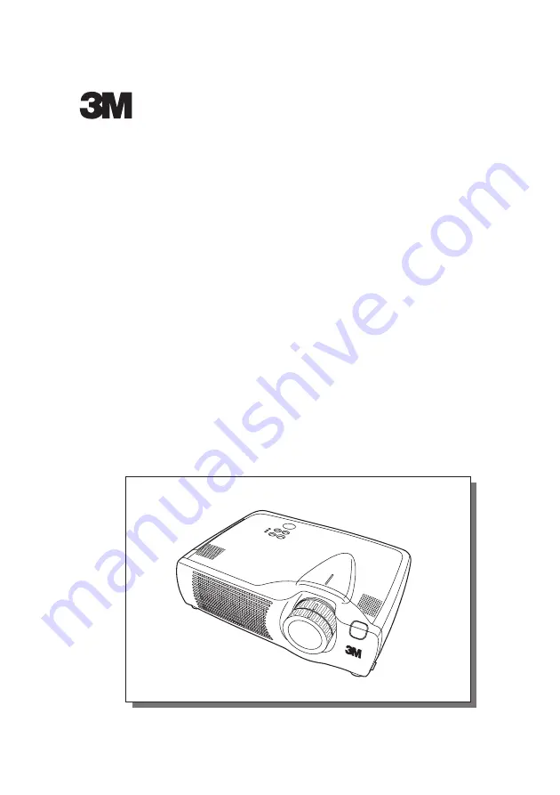
background image

MP8765
Multimedia Projector

Operator's Guide

MP8765 Projecteur multimedia - Guide de L' opérateur

MP8765 Multimedia-Projektor - Benutzerhandbuch

MP8765 Proyector de Multimedia - Guía del usuario

MP8765 Proiettore Multimediale - Guida dell' operatore

MP8765 Multimedia Projector - Gebruiksaanwijzing

MP8765 Projector dos Multimedia - Guia da operador

MP8765 Multimedia Projektør- Brukerhåndbok

3M

 MP

8765

3M™ Multimedia Projector 8765

© 3M 2002.  All Rights Reserved. 

Summary of Contents for Multimedia Projector MP8765

Page 1: ...enutzerhandbuch MP8765 Proyector de Multimedia Guía del usuario MP8765 Proiettore Multimediale Guida dell operatore MP8765 Multimedia Projector Gebruiksaanwijzing MP8765 Projector dos Multimedia Guia da operador MP8765 Multimedia Projektør Brukerhåndbok 3 M M P 8 7 6 5 3M Multimedia Projector 8765 3M 2002 All Rights Reserved ...

Page 2: ... could damage the projector peripheral equipment and or create a potentially unsafe operating condition 3M Multimedia projectors are designed to operate in a normal office environment 16 to 29 C 60 to 85 F 10 80 RH without condensation 0 1828 m 0 6000 feet above sea level The ambient operating environment should be free of airborne smoke grease oil and other contaminates that can affect the operat...

Page 3: ... Message 20 Table 10 Indicators Message 21 Table 11 Symptom 22 Table 12 Specifications 23 For TECHNICAL see the end of this manual The information in this manual is subject to change without notice The manufacturer assumes no responsibility for any errors that may appear in this manual The reproduction transmission or use of this document or contents is not permitted without express written author...

Page 4: ...aterial for future reshipment NOTE Projector STANDBY ON LASER BLANK RGB VIDEO AUTO MENU MENU SELECT KEYSTONE RESET FREEZE PinP MAGNIFY POSITION OFF VOLUME MUTE Remote Control Transmitter Batteries for Remote Control Transmitter Power Cord US UK Europe VGA Cable Component Video Cable with green lead MP8765 Multimedia Projector Product Safety Guide MP8765 Projecteur multimedia Guide de Securite de P...

Page 5: ... Cooling Fan INPUT Button LAMP Indicator TEMP Indicator POWER Indicator RESET Button MENU Button Ventilation Openings exhaust REAR RIGHT VIEW OF THE PROJECTOR Terminal Panel Refer below TERMINAL PANEL S VIDEO Terminal COMPONENT VIDEO Y Terminal CB PB Terminal CR PR Terminal VIDEO IN Terminal AUDIO IN R Terminal AUDIO IN L Terminal AUDIO IN 1 Terminal AUDIO IN 2 Terminal AUDIO OUT Terminal Remote C...

Page 6: ...ed to click the right mouse button RESET Button Used to click the right mouse button FREEZE Button MUTE Button PinP Button KEYSTONE Button VOLUME Button These functions work when the mouse control function is activated Remember the POSITION BLANK ON and MENU ON functions disable the mouse control function WARNING The laser pointer of the remote control transmitter is used in place of a finger or r...

Page 7: ...eries with this remote control transmitter Also do not mix new and old batteries This could cause battery cracking or leakage which could result in fire or personal injury When loading the batteries make sure the plus and minus terminals are correctly oriented as indicated in the remote control transmitter Incorrect orientation could cause battery cracking or leakage which could result in personal...

Page 8: ...able 1 Installation Reference a CAUTION Install the projector in a suitable environment according to instructions of the Product Safety Guide and this manual When you fix this unit with a metal tool and the like you must connect it with ground wire otherwise fire or electric shock can result Connect the ground terminal of AC inlet of this unit with the ground terminal provided at the building usin...

Page 9: ... for the USB cable The cables may have to be used with the core set to the projector side Use the cables which are included with the projector or specified Cabling Refer to the table below for connecting each terminal of the projector to a device Table 2 Cabling Function Terminal Cable RGB input RGB IN 1 VGA cable with D sub 15 pin shrink jack and inch thread screws RGB IN 2 RGB output RGB OUT DVI...

Page 10: ...igured with peripheral equipment including a computer display and an operating system This projector is recognized as a plug play monitor Use the standard display drivers Plug play may not operate by the computer to connect Use the RGB IN 2 terminal if plug play does not operate correctly NOTE NOTE ENGLISH 8 I I I IN N N NS S S ST T T TA A A AL L L LL L L LA A A AT T T TI I I IO O O ON N N N c c c...

Page 11: ... blinking 2 The system assumes the Standby mode when cooling is complete and the POWER indicator ceases blinking and changes to orange Check that the indicator is orange and set the power switch to O 3 The POWER indicator is extinguished when power is off Do not forget to attach the lens cap STANDBY ON LASER BLANK RGB VIDEO AUTO MENU MENU SELECT KEYSTONE RESET FREEZE PinP MAGNIFY POSITION OFF VOLU...

Page 12: ...l is input After approximately 10 seconds of inactivity the icon is extinguished and the POSITION mode is cleared automatically and buttons may operate as the mouse control button Refer to page 4 RESET Initialize Each Item Select an item and press the RESET button Initialize Position Adjustment Press the RESET button and the POSITION mode This function is valid only when RGB signal is input Valid ...

Page 13: ...ress the MENU SELECT button Allows the user to select the normal menu or the single menu Only the selected item is displayed on the single menu and other items are displayed with the and buttons as with the normal menu Valid only when the Setup menu is used Push the MENU SELECT button after selecting items such as BRIGHTNESS The MENU SELECT button may operate as the mouse control button Refer to p...

Page 14: ...IGHT Adjustment Dark Light CONTRAST Adjustment Weak Strong V POSIT Adjustment Down Up H POSIT Adjustment Left Right H PHASE Adjustment Left Right Adjust to eliminate flicker H SIZE Adjustment Small Large The image may not be displayed correctly if the horizontal size is excessive In such cases press the RESET button and initialize the horizontal size SHARPNESS Adjustment Soft Clear COLOR Adjustmen...

Page 15: ...s approximately 10 seconds It may not function correctly with some input signals Pressing the AUTO button in this case may correct this problem This function is the same as for the AUTO function in Basic operation RGB Displays RGB Input Frequency Displays the horizontal and vertical sync signal frequencies for RGB input Valid only at RGB input VIDEO Select Video Signal Type Select the signal type ...

Page 16: ...URN OFF displays the blue screen When MyScreen or ORIGINAL is selected the screen is going to the black after several minutes MyScreen Set MyScreen Mode Select the EXECUTE with the button to display the MyScreen menu and set the MyScreen mode for BLANK and START UP functions ESC clears and closes the menu box NORM is default of the MyScreen menu FREEZE freezes the image and displays the frame to c...

Page 17: ...in with the button When STOP is selected the system does not enter the standby mode even if no signal is received SYNC ON G SYNC ON G Valid Select TURN ON with the button SYNC ON G Invalid Select TURN OFF with the button May not be displayed correctly with some input signals when SYNC ON G is valid In such cases remove the signal connector so that no signal is received set SYNC ON G to invalid and...

Page 18: ...ode that the customer customized screen is displayed This is the blue screen at the factory setting Refer to the description of MyScreen below ORIGINAL is a mode that the factory fixed screen is displayed TURN OFF displays the blue screen When MyScreen or ORIGINAL is selected the screen is going to the black after several minutes MIRROR Select Mirror Status Select the mirror status with the button...

Page 19: ... power OFF wait approximately 20 minutes and switch power ON again If the LAMP indicator is still red replace the lamp NOTE WARNING For disposal of used lamp treat according to the instruction of community authorities Since the lamp is made of glass do not apply shock to it and do not scratch it Also do not use old lamp This could also cause explosion of the lamp Premature lamp failure MAY be caus...

Page 20: ...p timer after replacing the lamp When the lamp has been replaced after the LAMP indicator is red or the CHANGE THE LAMP message is displayed complete the following operation within ten minutes of switching power ON The power will be turned off automatically in over 10 minutes 1 Switch power ON and press the RESET button for approximately three seconds The LAMP xxxx hr message will appear on the la...

Page 21: ...h power OFF and remove the power cord from the power outlet before beginning maintenance work Please read the Product Safety Guide thoroughly to ensure that maintenance is performed correctly Do not use detergents or chemicals other than those noted above e g benzene or thinners Do not use cleaning sprays Do not rub with hard materials or tap the equipment CAUTION Switch power OFF and remove the p...

Page 22: ...automatically in hours Replace the lamp as shown in P 17 18 Lamp Always reset the lamp timer after replacing the lamp CHANGE THE LAMP AFTER REPLACING LAMP RESET THE LAMP TIME THE POWER WILL TURN OFF AFTER 0 hr The usage time of lamp is about to reach Power will be switched OFF in a few minutes 2 Switch power OFF immediately and replace the lamp as shown in P 17 18 Lamp Always reset the lamp timer ...

Page 23: ...f Lamp or lamp cover is not found or hasn t been fitted in correctly Switch power OFF and wait for 45 minutes until the equipment cools Check fitting of the lamp and lamp cover and switch power ON again Contact your dealer if the same problem occurs again Blinks Lights red Turns off Blinks red The cooling fan is not operating Switch power OFF and wait for 20 minutes until the equipment cools Check...

Page 24: ...is not correctly connected Connect correctly 7 8 The volume is set to minimum Press VOLUME on the remote control or display the menu screen and adjust the volume 11 15 Mute is turned on Press the MUTE button 11 Audio is present but no video The projector is not correctly connected Connect correctly 7 8 The brightness adjustment knob is rotated fully clockwise Select BRIGHT with the MENU button and...

Page 25: ...jack 2 DVI TMDS DC 150 1200 mV AC 1 56 Vp p TTL Level Positive Negative AUDIO IN RGB1 200mVrms 50 kΩ max 3 0Vp p Stereo mini jack DVI RGB2 Video signal input VIDEO IN 1 0Vp p 75Ω terminator RCA jack S VIDEO IN Brightness signal 1 0Vp p 75Ω terminator Color signal 0 286Vp p NTSC burst signal 75Ω terminator 0 300Vp p PAL SECAM burst signal 75Ω terminator Mini DIN 4 pin jack COMPONENT VIDEO Y 1 0 Vp ...

Page 26: ...Adapter 78 8118 3308 2 How to Order Please order these parts through your dealer or contact 3M Customer Service at the following number In U S or Canada 1 800 328 1371 In other locations contact your local 3M sales office Mouse Cable PS 2 78 8118 8105 7 Mouse Cable Serial 78 8118 8107 3 Remote Control Transmitter 78 8118 8970 4 Not Included with Basic Packet Part Number Ceiling mount 78 6969 9549 ...

Page 27: ...al 75Ω terminator 0 300Vp p PAL SECAM burst signal 75Ω terminator 2 Brightness 1 0Vp p 75Ω terminator 3 Ground 4 Ground Signal Connector Pin Assignment 1 D sub 15 pin Shrink Connector RGB IN 1 RGB IN 2 RGB OUT 1 2 3 4 5 6 7 8 9 10 11 12 13 14 15 Pin No Signal Pin No Signal Pin No Signal 1 T M D S Data 2 11 T M D S Data 1 3 Shield 21 2 T M D S Data 2 12 22 T M D S Clock Shield 3 T M D S Data 2 4 Sh...

Page 28: ...rate NOTE Resolution H V fH kHz fV Hz Rating Signal mode Display mode 640 350 37 9 85 1 VESA VGA 1 Zoom in 640 400 37 9 85 1 VESA VGA 2 Zoom in 720 400 37 9 85 0 VESA TEXT Zoom in 640 480 31 5 59 9 VESA VGA 60Hz Zoom in 640 480 35 0 66 7 Mac13 mode Zoom in 640 480 37 9 72 8 VESA VGA 72Hz Zoom in 640 480 37 5 75 0 VESA VGA 75Hz Zoom in 640 480 43 3 85 0 VESA VGA 85Hz Zoom in 800 600 35 2 56 3 VESA ...

Page 29: ...2 2 0 7 SVGA 60Hz 3 2 2 2 20 0 1 0 SVGA 72Hz 2 4 1 3 16 0 1 1 SVGA 75Hz 1 6 3 2 16 2 0 3 SVGA 85Hz 1 1 2 7 14 2 0 6 Mac 16 mode 1 1 3 9 14 5 0 6 XGA 60Hz 2 1 2 5 15 8 0 4 XGA 70Hz 1 8 1 9 13 7 0 3 XGA 75Hz 1 2 2 2 13 0 0 2 XGA 85Hz 1 0 2 2 10 8 0 5 1152 864 75Hz 1 2 2 4 10 7 0 6 1280 960 60Hz 1 0 2 9 11 9 0 9 1280 1024 60Hz 1 0 2 3 11 9 0 4 1280 1024 75Hz 1 1 1 8 9 5 0 1 Computer Signal Vertical s...

Page 30: ...vailable USB cable Consult your dealer to get the cable if you need 2 Start the mouse function Refer to the descriptions of DISC PAD and MOUSE RIGHT button of page 4 Before connecting read the instruction manuals of the devices to be connected In the case of notebook type computers with an internal pointing device the mouse control function will not work unless the internal pointing device is disa...

Page 31: ... 7 10 9 12 11 14 13 15 RTS GND 5V ADB GND 5V POWER ON DATA 2 1 4 3 Mouse jack Mini DIN 4 pin Projector Computer 1 2 3 4 5 6 7 8 9 10 11 12 13 14 15 CONTROL Terminal D sub 15 pin shrink jack Serial Mouse 2 1 4 3 6 5 2 1 4 3 6 5 8 7 10 9 8 7 9 12 11 14 13 15 RI CD RD TD DTR GND DSR CTS RTS RTS GND SEL0 TD 2 1 4 3 6 5 8 9 7 Mouse jack D sub 9 pin Projector Computer 1 2 3 4 5 6 7 8 9 10 11 12 13 14 15...

Page 32: ...D DSR RTS CTS RI 1 2 3 4 5 6 7 8 9 RS 232C jack D sub 9 pin Projector Computer Communications setting 19200bps 8N1 1 Protocol Consist of header 7 bytes command data 6 bytes 2 Header BE EF 03 06 00 CRC_low CRC_high CRC_low Lower byte of CRC flag for command data CRC_high Upper byte of CRC flag for command data 3 Command data byte_0 byte_1 byte_2 byte_3 byte_4 byte_5 Action Type Setting code low hig...

Page 33: ...se code 06H to the computer Decreasing the projector setting value Decrement command 1 The computer sends the decrement code Header Command data 05H 00H type 2 bytes 00H 00H to the projector 2 The projector decreases the setting value on the above setting code 3 The projector returns the response code 06H to the computer When a command sent by the projector cannot be understood by the computer Whe...

Page 34: ...0 Orange BE EF 03 06 00 EF D2 01 00 03 30 01 00 Green BE EF 03 06 00 1F D2 01 00 03 30 02 00 Blue BE EF 03 06 00 8F D3 01 00 03 30 03 00 Purple BE EF 03 06 00 BF D1 01 00 03 30 04 00 Transparent BE EF 03 06 00 2F D0 01 00 03 30 05 00 Gray BE EF 03 06 00 DF D0 01 00 03 30 06 00 Get BE EF 03 06 00 4C D3 02 00 03 30 00 00 Startup Set ORIGNAL BE EF 03 06 00 0B D2 01 00 04 30 00 00 OFF BE EF 03 06 00 9...

Page 35: ...0 00 Keystone_H Reset Execute BE EF 03 06 00 98 D8 06 00 20 70 00 00 Auto Execute BE EF 03 06 00 91 D0 06 00 0A 20 00 00 Blank on off Set off BE EF 03 06 00 FB D8 01 00 20 30 00 00 on BE EF 03 06 00 6B D9 01 00 20 30 01 00 Get BE EF 03 06 00 C8 D8 02 00 20 30 00 00 Error Status Get BE EF 03 06 00 D9 D8 02 00 20 60 00 00 Example of Return 00 00 01 00 02 00 03 00 Normal Cover error Fan error Lamp er...

Page 36: ...ent BE EF 03 06 00 0E D2 05 00 07 20 00 00 Keystone_H Get BE EF 03 06 00 E9 D0 02 00 0B 20 00 00 Increment BE EF 03 06 00 8F D0 04 00 0B 20 00 00 Decrement BE EF 03 06 00 5E D1 05 00 0B 20 00 00 Aspect Set 4 3 Full BE EF 03 06 00 9E D0 01 00 08 20 00 00 16 9 BE EF 03 06 00 0E D1 01 00 08 20 01 00 Small BE EF 03 06 00 FE D1 01 00 08 20 02 00 Get BE EF 03 06 00 AD D0 02 00 08 20 00 00 Display Positi...

Page 37: ... 00 00 HDTV Set 1080i BE EF 03 06 00 F2 73 01 00 05 22 00 00 1035i BE EF 03 06 00 62 72 01 00 05 22 01 00 Get BE EF 03 06 00 C1 73 02 00 05 22 00 00 PinP Size Set off BE EF 03 06 00 FE 22 01 00 00 23 00 00 Large BE EF 03 06 00 6E 23 01 00 00 23 01 00 Small BE EF 03 06 00 9E 23 01 00 00 23 02 00 Get BE EF 03 06 00 CD 22 02 00 00 23 00 00 PinP Position Set Upper left BE EF 03 06 00 02 23 01 00 01 23...

Page 38: ...2 00 Get BE EF 03 06 00 F4 F0 02 00 A1 30 00 00 IR Remote Front Set off BE EF 03 06 00 FF 32 01 00 00 26 00 00 on BE EF 03 06 00 6F 33 01 00 00 26 01 00 Get BE EF 03 06 00 CC 32 02 00 00 26 00 00 IR Remote Rear Set off BE EF 03 06 00 03 33 01 00 01 26 00 00 on BE EF 03 06 00 93 32 01 00 01 26 01 00 Get BE EF 03 06 00 30 33 02 00 01 26 00 00 IR Remote Top Set off BE EF 03 06 00 47 33 01 00 02 26 00...

Page 39: ...T T T TE E E EC C C CH H H HN N N NI I I IC C C CA A A AL L L L c c c co o o on n n nt t t ti i i in n n nu u u ue e e ed d d d 3M Multimedia Projector 8765 3M 2002 All Rights Reserved ...

Page 40: ...G Intended Use Before operating this machine please read this entire manual thoroughly The 3MTM Multimedia Projectors are designed built and tested for use indoors using 3M lamps 3M ceiling mount hardware and nominal local voltages The use of other replacement lamps outdoor operation or different voltages has not been tested and could damage the projector peripheral equipment and or create a poten...

Reviews: