background image

North American - ENG

Date Released:

10-20-20

3M-Matic

 Accuglide V HSP - 2 Inch Taping Head - Type 12000     

Page 13

44-0009-2157-5 / ECO#0086964

Maintenance   

(continued)

Cleaning


Regular slotted containers produce a  


great deal of dust and paper chips  


when conveyed through  taping heads.   


If this dust is allowed to build-up on the  


heads, it can cause wear on the moving  


parts.  Excessive dirt build-up should  


be wiped off with a damp cloth. 


Cleaning should be done once per 


month, depending on the number 


and type of boxes used. If the boxes  


used are dirty, or if the environment 


in which the heads operate is dusty,  


cleaning on a more frequent basis  


may be necessary. 


Note – 

Never attempt to remove dirt  


from taping heads by blowing it out  


with compressed air.  This can cause  


the dirt to be blown inside components  


onto sliding surfaces.  Dirt in these  


areas can cause serious equipment  


damage.  Never wash down or subject  


taping heads to conditions causing  


moisture condensation on components. 


   Serious equipment damage could  

  result.


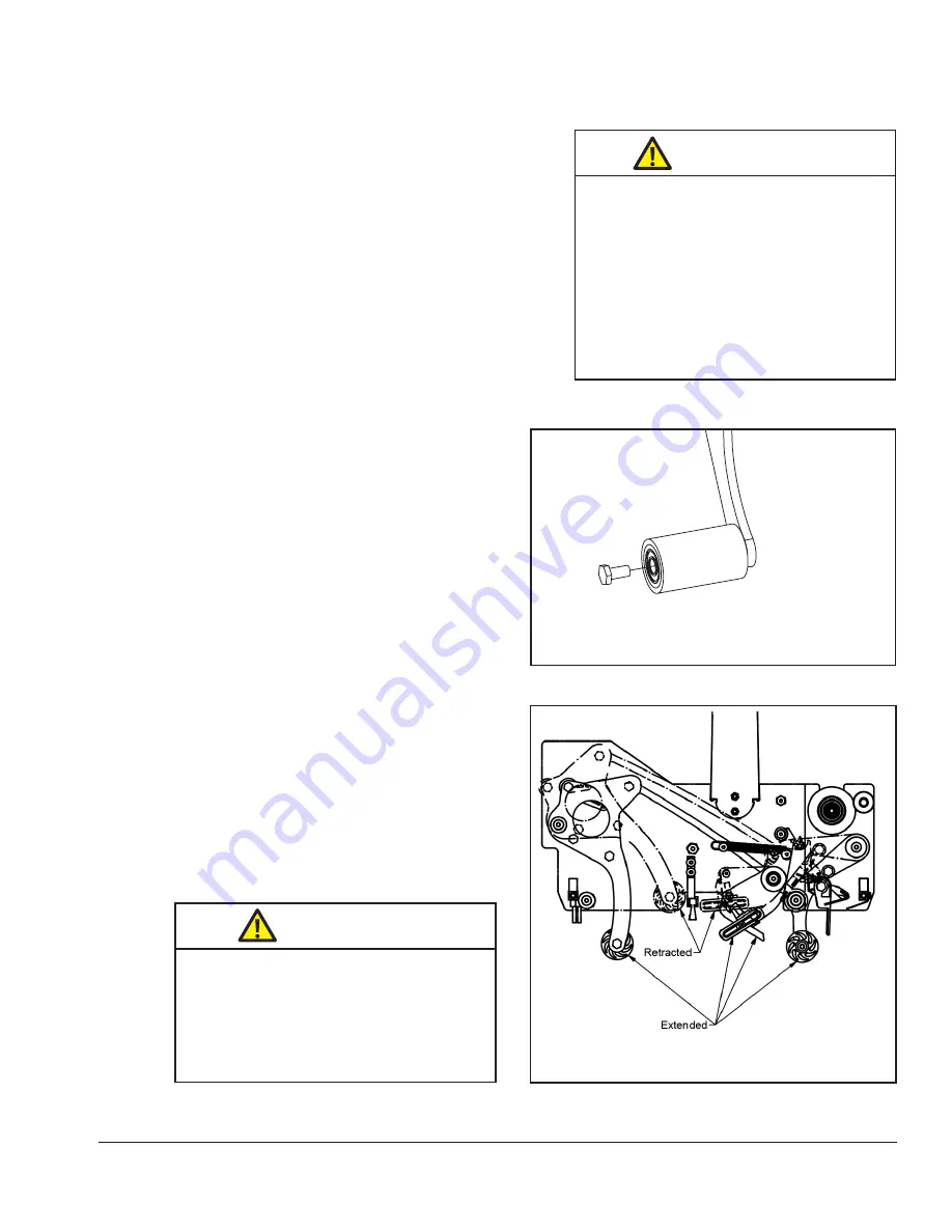
Applying / Buffing Roller Replacement


Replacing roller requires removal of the  


mounting screw 

(Figure 4-2 - also see  


Parts List). 

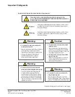
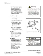
•  To reduce the risk associated with    

  shear, pinch, and entanglement hazards

 -  T

urn air and electrical supplies off 


     on associated equipment before 

 performing any adjustments, mainte-

  nance, or servicing the taping heads

-  Never attempt to work on the taping  

   head or load tape while the box drive  

   system is running

 Warning

• To reduce the risk associated with 

sharp blade hazards:

-   Keep hands and fingers away from 

tape cutoff blades under orange blade 

guards.  The blades are extremely sharp.

 Warning

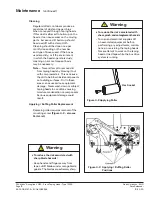
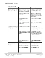
Figure 4-3   Applying / Buffing Roller    

 Positions

Hex Socket

Figure 4-2 Applying Roller

Summary of Contents for Accuglide V HSP

Page 1: ...THIS EQUIPMENT Read understand and follow all safety and operating instructions Spare Parts It is recommended you immediately order the spare parts listed in the Spare Parts Service Information section These parts are expected to wear through normal use and should be kept on hand to minimize production delays 3M Matic Accuglide V HSP Type 12000 Taping Heads 2 Inch Serial For reference record machi...

Page 2: ...North American ENG Date Released 10 20 20 3M Matic Accuglide V HSP 2 Inch Taping Head Type 12000 Page ii 44 0009 2157 5 ECO 0086964 ...

Page 3: ...rder replacement parts contact us CSPD division of Combi Packaging Systems LLC Phone 1 800 344 9883 5365 East Center Dr N E Fax 1 877 847 5883 Canton OH 44721 e mail CSPD CSR combi com www combi com 3M Matic TM 3M Company St Paul MN 55144 USA Model Part Number Electrical Drawing Type Serial Number Indoor Industrial use only 4000563 INTERTEK SCCR Volt Hertz Air Supply IP Ampere Phase Watt Air Consu...

Page 4: ...North American ENG Date Released 10 20 20 3M Matic Accuglide V HSP 2 Inch Taping Head Type 12000 Page iv 44 0009 2157 5 ECO 0086964 ...

Page 5: ...equipment you ordered It has been set up and tested in the factory with Scotch tapes Included with each machine is an Instructions and Parts List Manual Order parts by part number part description and quantity required Also when ordering parts or additional manuals include model machine name machine type and serial number that are located on the identification plate Service replacement parts and a...

Page 6: ...North American ENG Date Released 10 20 20 3M Matic Accuglide V HSP 2 Inch Taping Head Type 12000 Page vi 44 0009 2157 5 ECO 0086964 ...

Page 7: ...afeguards 4 5 Specifications 6 7 Dimensional Drawing 7 Installation 8 Receiving and Handling 8 Installation Guidelines 8 Tape Leg Length 8 Tape Width Adjustment 8 Operation 9 11 Tape Loading Taping Head 10 11 Maintenance 12 13 Blade Replacement 12 Blade Guard 12 Blade Oiler Pad 12 Cleaning 13 Applying Buffing Roller Replacement 13 Adjustments 14 15 Tape Latch Alignment 14 Tape Drum Friction Brake ...

Page 8: ...under shall be given to 3M solely through the 3M Matic Help line To be entitled to repair or replacement as provided under this warranty the part must be returned as directed by 3M to its factory or other authorized service station designated by 3M If 3M is unable to repair or replace the part within a reasonable time after receipt thereof 3M at its option will replace the equipment or refund the ...

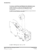
Page 9: ...pressure sensitive film box sealing tape to the top and or bottom center seam ofregular slotted containers The compact size and simplicityofthe taping head makes it suitable for mounting in box conveying systems otherthan 3M Matic case sealers This includes replacement ofothertypes oftaping gluing or stapling heads in existing case sealing machines The VHSP 2 Inch Type 12000 Upperand LowerTaping H...

Page 10: ...North American ENG Date Released 10 20 20 3M Matic Accuglide V HSP 2 Inch Taping Head Type 12000 Page 2 44 0009 2157 5 ECO 0086964 ...

Page 11: ...ntained in perfect condition and operated safely Ensure that the manual is available to all operators of this equipment and the manual is kept up to date with all subsequent amendments Should the equipment be sold or disposed of please ensure that the manual is passed on with the machine Electrical and pneumatic diagrams are included in the manual Equipment using PLC controls and or electronic com...

Page 12: ...perating or servicing the case sealer Allow only properly trained and qualified personnel to operate and or service this equipment Caution To reduce the risk associated with muscle strain Use proper body mechanics when removing or installing taping heads that are moderately heavy or may be considered awkward to lift To reduce the risk associated with impact hazards Place the taping head on a smoot...

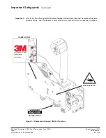
Page 13: ...86964 Figure 1 1 Replacement Labels 3M Part Numbers Important Safeguards continued 78 8070 1335 0 78 0025 1903 7 Important In the event the following safety labels are damaged or destroyed they must be replaced to ensure operator safety See Replacement Parts Illustrations and Parts Lists for label part numbers 78 8137 0223 6 ...

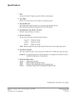
Page 14: ...ength Standard 50 8mm 6mm 2 inches 1 4 inch 5 Box Size Capacities For use with center seam regular slotted containers Length 150mm 6 inches Height 101mm 4 inches Width 150mm 6 inches Note Box size capacities may also be determined by the case conveying system used 6 Operating Conditions Use in dry relatively clean environments at 5 to 40 C 40 to 105 F with clean dry boxes Important Taping heads sh...

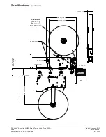
Page 15: ...continued 406 4 mm 16 00 in Maximum Roll Diameter 350 0 mm 13 78 in 400 0 mm 15 75 in 79 5 mm 3 13 in 203 7 mm 8 02 in 152 0 mm 5 98 in 18 0 mm 71 in 37 5 mm 1 48 in 101 6 mm 4 00 in Minimum Standard Head Spacing 72 4 mm 2 85 in 586 5 mm 23 09 in 383 3 mm 15 09 in 142 9 mm 5 63 in Box Direction 3 2 mm 13 in Max 3 2 mm 13 in Max M6 Mounting Holes ...

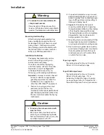
Page 16: ... conveyor to prevent pusher from contacting apply ing or buffing roller arms resulting in damage to taping head 3 Figure 2 1 illustrates the typical mounting relationship for opposing taping head assemblies to allow taping of box heights see specifications The taping heads must be completely staggered so only one tape seal is being applied at one time 4 Mounting studs are provided with the taping ...

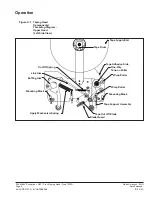
Page 17: ...6964 Operation Tape Supply Roll Tape Drum Tape Adhesive Side Wrap Roller Wrap Roller Mounting Block Mounting Block Tape Support Assembly Tape Cut Off Blade Blade Guard Apply Mechanism Spring Cut Off Spring One Way Tension Roller Buffing Arm Link Arm Figure 3 1 Taping Head Components Threading Diagram Upper Head Left Side View ...

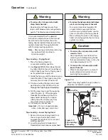
Page 18: ...the tape should be facing the tension roller at position 2 and away from the guide roller at position 3 6 Cut away any excess tape Important Do not cut against apply roller roller damage could occur Tape Loading Lower Taping Head 1 Remove the lower taping head from the conveyor bed or associated equipment and place it a convenient working position 2 Lower taping head is loaded and threaded in same...

Page 19: ...Seat tape roll fully against back flange of drum Adhere tape lead end to threading needle as shown Manually turn tape roll to create slack tape while pulling threading needle through tape applying mechanism until needle is through and tape is in alignment with applying roller Excess tape can be cut with a scissors at applying roller To reduce the risk associated with sharp blade hazards Keep hands...

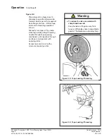
Page 20: ... slowly pivoting blade guard back Blade Guard The blade guard covers the blade whenever a box is not being taped Periodically check to be sure the blade guard is functioning properly and returning to cover the blade Replace any defective parts Blade Oiler Pad To reduce adhesive build up the taping heads are equipped with a factory pre lubricated felt oiler pad that provides a film of oil on the cu...

Page 21: ...cause the dirt to be blown inside components onto sliding surfaces Dirt in these areas can cause serious equipment damage Never wash down or subject taping heads to conditions causing moisture condensation on components Serious equipment damage could result Applying Buffing Roller Replacement Replacing roller requires removal of the mounting screw Figure 4 2 also see Parts List To reduce the risk ...

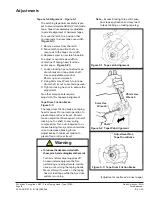
Page 22: ...pe drum bracket on tape drum shaft Use an adjustable wrench or 25mm open end wrench 2 Using 5mm Hex Wrench turn tape drum shaft in out to center tape web 3 Tighten locking hex nut to secure the adjustment No other components require adjustment for tape web alignment Tape Drum Friction Brake Figure 5 3 The tape drum friction brake on taping head is pre set for normal operation to prevent tape roll ...

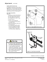
Page 23: ...ap a cord or small strap non adhesive 4 6 turns around the tension roller 2 Attach a spring scale to the end of the cord or strap 3 Turn adjusting nut with socket wrench provided until required force of approximately 0 5 kg to 0 9 kg 1 to 2 lbs is reached to turn roller pulling on spring scale Adjustments continued on next page Adjustments continued To reduce the risk associated with shear pinch a...

Page 24: ...North American ENG Date Released 10 20 20 3M Matic Accuglide V HSP 2 Inch Taping Head Type 12000 Page 16 44 0009 2157 5 ECO 0086964 Notes ...

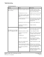
Page 25: ...r before going around the one way tension roller Adjust the one way tension roller Adjust the tape web alignments Position the roller in its mounting slot so that the tape extends just beyond the centerline of the applying roller Check leg length adjustments Replace the blade Increase tape tension by adjusting the one way tension roller Clean and adjust the blade Make sure the blade is bottomed ou...

Page 26: ... applying mechanism to its rest position The one way tension roller is defective Tape drum not centered Centering guides not centered Box flaps not of equal length Correction Adjust the one way tension roller and or the tape drum assembly Clean adhesive deposits from the surface ends and shafts of the rollers Then lubricate roller shafts Remove all lubricant from roller surfaces Refer to tape cutt...

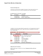
Page 27: ... In addition to the tools included with the taping head are a list of suggested spare parts that should be ordered and kept on hand These parts will require replacement under normal wear of the tape head Qty Part Number Description 2 78 0025 1838 5 Roller Apply Buff AG V HSP 2 1 78 8113 7030 9 Spring Torsion Blade Guard 1 78 8062 3993 1 Blade 1 78 0025 1814 6 Upper Spring Silver 1 78 0025 1815 3 L...

Page 28: ...North American ENG Date Released 10 20 20 3M Matic Accuglide V HSP 2 Inch Taping Head Type 12000 Page 20 44 0009 2157 5 ECO 0086964 ...

Page 29: ...quired and the parts reference number 3 The replacement parts list that follows each illustration includes the part number and part description for the parts in that illustration Note The complete description has been included for standard fasteners and some commercially available components This has been done to allow obtaining these standard parts locally should the customer elect to do so 4 Ref...

Page 30: ...North American ENG Date Released 10 20 20 3M Matic Accuglide V HSP 2 Inch Taping Head Type 12000 Page 22 44 0009 2157 5 ECO 0086964 ...

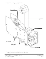
Page 31: ...Accuglide V HSP 2 Inch Taping Head Type 12000 Page 23 44 0009 2157 5 ECO 0086964 Accuglide V HSP 2 Taping Head Type 12000 Taping Head Assembies AccuGlide NPH 2 Inch Type 12000 Figure 16103 Figure 16098 Figure 16100 Figure 16099 Figure 16102 Figure 16109 ...

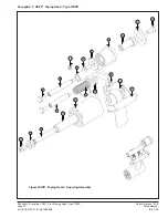
Page 32: ...0 20 20 3M Matic Accuglide V HSP 2 Inch Taping Head Type 12000 Page 24 44 0009 2157 5 ECO 0086964 Accuglide V HSP 2 Taping Head Type 12000 Figure 16100 Taping Head Applying Assembly 18 15 16 10 14 13 11 17 19 20 1 6 5 9 4 8 2 12 3 18 7 ...

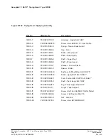
Page 33: ...5 Shaft Roller Apply 16100 7 78 8137 5695 0 Shaft Finger Pivot 16100 8 78 8137 5696 8 Shaft Wrap Swivel 16100 9 78 8137 5753 7 Washer Friction Plastic 16100 10 78 8137 5691 9 Spacer Roller 16100 11 78 0025 1833 6 Bushing Buffing Roller AG V HSP 2 16100 12 78 0025 1838 5 Roller Apply Buff AG V HSP 2 16100 13 78 0025 1840 1 Fork Formed AG V HSP Cntrl Side 2 16100 14 78 0025 1801 3 Shaft Pivot Apply ...

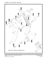
Page 34: ...Released 10 20 20 3M Matic Accuglide V HSP 2 Inch Taping Head Type 12000 Page 26 44 0009 2157 5 ECO 0086964 Accuglide V HSP 2 Taping Head Type 12000 Figure 16099 Taping Head Buffing Assembly 9 5 4 6 1 2 10 15 13 11 14 12 8 3 7 ...

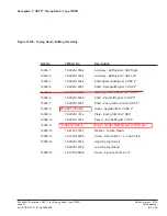
Page 35: ... 2 16099 5 78 0025 1833 6 Bushing Buffing Roller AG V HSP 2 16099 6 78 0025 1836 9 Shaft Pivot Buffing AG V HSP 2 16099 7 78 0025 1837 7 Shaft Link Arm Mount AG V HSP 2 16099 8 78 0025 1838 5 Roller Apply Buff AG V HSP 2 16099 9 78 0025 1761 9 Plate Spring Hldr AG V HSP 16099 10 78 0025 1762 7 Spacer Brz Buffing AG V HSP 16099 11 78 8137 5693 5 Shaft Roller Apply 16099 12 78 8137 5753 7 Washer Fri...

Page 36: ...0 20 3M Matic Accuglide V HSP 2 Inch Taping Head Type 12000 Page 28 44 0009 2157 5 ECO 0086964 Accuglide V HSP 2 Taping Head Type 12000 Figure 16102 Taping Head Blade Guard Assembly 2 7 3 19 5 8 9 6 4 13 15 12 18 10 21 1 15 14 16 11 17 20 ...

Page 37: ...ff AG V HSP 16102 7 78 8113 7076 1 Bushing 16102 8 26 1003 7953 1 Screw Soc Hd M5 x 30 16102 9 78 8028 8214 8 Washer Triple M5 16102 10 78 8137 7093 6 Screw Butt Soc Hd M4 07 x 6 Zinc Plt 16102 11 78 8137 5684 4 Cap Pivot 16102 12 26 1003 8596 7 Screw Hex Hd M5 x 8 w Ext Tth Lck Wsh 16102 13 78 8052 6602 6 Spring Cutter 16102 14 26 1001 9843 6 Screw Flat Soc Hd M6 x 16 16102 15 26 1005 4758 2 Scre...

Page 38: ... Taping Head Type 12000 Page 30 44 0009 2157 5 ECO 0086964 Accuglide V HSP 2 Taping Head Type 12000 Figure 16098 Taping Head Frame Assembly Version 2 Version 1 Little David 17 9 19 20 21 25 16 18 10 14 11 26 23 22 24 13 15 4 5 8 2 1 7 6 3 35 27 26 27 32 31 36 33 34 28 29 30 ...

Page 39: ...821 1 Shaft Tension Roller AG V HSP 2 16098 17 78 8137 5897 2 Bumper Stop 10x15x10 16098 18 78 0025 1736 1 Disk Assy TAM AG V HSP 16098 19 78 0025 1822 9 Shaft Spring Main AG V HSP 2 16098 20 78 0025 1740 3 Frame Wldmnt AG V HSP Cntrl Side 16098 21 78 0025 1823 7 Shaft Cross Frame AG V HSP 2 16098 22 78 0025 1824 5 Shaft Cross Bumper AG V HSP 2 16098 23 78 0025 1825 2 Brush Assy Mid AG V HSP 2 160...

Page 40: ...d 10 20 20 3M Matic Accuglide V HSP 2 Inch Taping Head Type 12000 Page 32 44 0009 2157 5 ECO 0086964 Accuglide V HSP 2 Taping Head Type 12000 Figure 16103 Upper and Lower Taping Head Tape Drum Arm Assembly 10 12 11 6 7 8 9 3 5 1 4 2 ...

Page 41: ...g AG V HSP 16103 2 78 8017 9169 6 Nut M18x1 3877 7 3894 7 4046 16 16103 3 78 0025 1911 0 Latching Tape Drum 2 16103 4 26 1005 6859 6 Nut Self Locking M5 16103 5 26 0001 5862 1 Screw Flat Hd Soc M5 x 12 16103 6 26 1004 5510 9 Washer Plain M10 X 20 X 2 5 16103 7 78 0025 0172 0 Nut Self Locking M10 X 1 16103 8 78 8052 6271 0 Washer Tape Drum 16103 9 78 8060 8172 1 Washer Friction 16103 10 78 8098 882...

Page 42: ...ased 10 20 20 3M Matic Accuglide V HSP 2 Inch Taping Head Type 12000 Page 34 44 0009 2157 5 ECO 0086964 Accuglide V HSP 2 Taping Head Type 12000 Figure 16109 Upper and Lower Taping Head Blade Retract Assembly 3 2 4 5 6 1 7 8 9 10 ...

Page 43: ...port 58 x 40 16109 2 78 0025 0499 7 Fitting 6 mm x 1 8 90 Elbow Male NPT 16109 3 26 0001 9843 6 Screw Flat Soc Hd M6 X 16 16109 4 26 1000 0010 3 Washer Plain M6 16109 5 78 0025 1791 6 Cylinder ISO 6432 D 20 C 25 C85N20 25 16109 6 78 8091 0418 1 Nut Self Locking M6 16109 7 78 0025 1792 4 Bumper 1 4 28 Female Round 16109 8 78 0025 0498 9 Nut 1 4 28 Hex Jam PLT 16109 9 70 8000 5374 9 Nut 1 2 13 Hex J...

Page 44: ...North American ENG Date Released 10 20 20 3M Matic Accuglide V HSP 2 Inch Taping Head Type 12000 Page 36 44 0009 2157 5 ECO 0086964 ...

Page 45: ...North American ENG Date Released 10 20 20 3M Matic Accuglide V HSP 2 Inch Taping Head Type 12000 Page 37 44 0009 2157 5 ECO 0086964 ...

Page 46: ...38 ...
Reviews: