Installation and Operating Instructions For
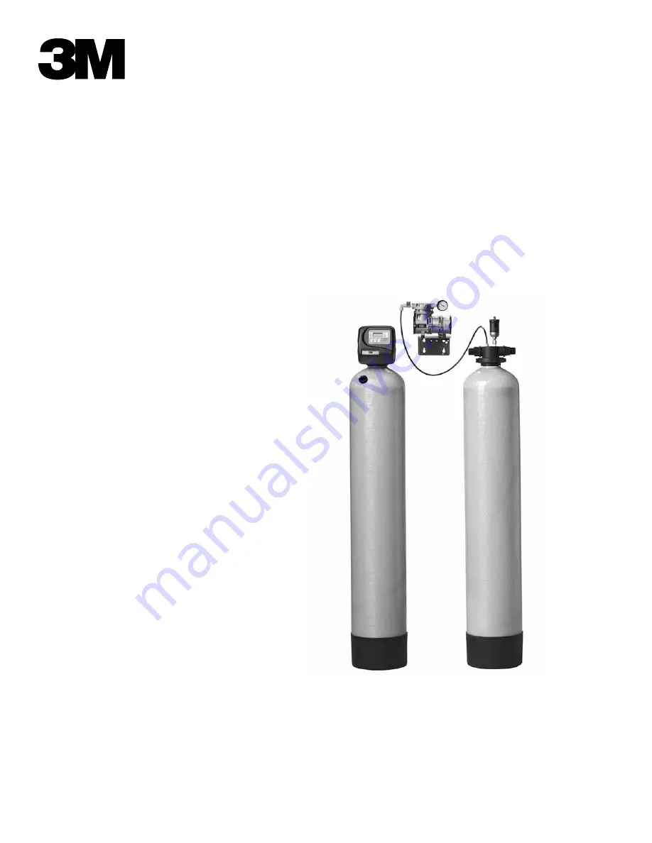
3M™ Iron Reduction Filtration Systems
MODELS:
3MAPPM1503MAPPM200
Homeowner: Please retain for operation and future maintenance instructions.
Page 1: ...Installation and Operating Instructions For 3M Iron Reduction Filtration Systems MODELS 3MAPPM150 3MAPPM200 Homeowner Please retain for operation and future maintenance instructions ...
Page 2: ......
Page 3: ...used in this product depending upon the application During installation dust may cause irritation to skin eyes and respiratory tract Utilize a NIOSH approved dust filter mask protective gloves and appropriate eye protection when handling and pouring gravel and filter media To request an MSDS relating to this product call 203 238 8965 or go to www 3M com select country and use the search engine to ...
Page 4: ... produces an iron reduction capacity from 30 000 to 50 000 parts per million ppm compared to 6 000 to 8 000 ppm for chemical oxidation processes The media DOES NOT require a chemical regenerant such as potassium permanganate for oxygen enrichment salt chlorine or any other chemicals The 3MAPPM Series Iron Reduction Filtration System automatically adjusts the pH to neutral or higher on acid water W...
Page 5: ...pon which the bacteria may live thus minimizing its effects pH The pH of water is a measurement of Hydrogen Ion concentration in water Water with a pH of less than 7 0 is acidic above 7 0 it is base and a pH of 7 0 is neutral The lower the pH value the greater the acidity and the higher the pH value the more base Acidic water pH less than 7 0 is corrosive to pipes ap pliances etc A pH of 7 0 or hi...
Page 6: ...g out buildings or other high demand applications the purchase of an FS1 Flow Switch is suggested Instructions accompanying the flow switch will describe the proper installation for these types of applications THE IMPORTANCE OF YOUR PRESSURE TANK The 3MAPPM Series Iron Reduction Filtration System will perform satisfactorily with either a captive air bladder type pressure tank or a standard air to ...
Page 7: ...YSTEM PRESSURE REGULATOR NOT SUPPLIED PRESSURE REGULATOR NOT SUPPLIED FS1 FLOW SWITCH CHECK VALVE CHECK VALVE CHECK VALVE BRINE TANK FILTERED WATER FILTERED SOFT WATER TANK AERATION BRINE TANK FILTERED WATER FILTERED SOFT WATER TANK AERATION FS1 FLOW SWITCH PRESSURE REGULATOR NOT SUPPLIED TYPICAL INSTALLATION SPLIT STREAM INSTALLATION PUBLIC WATER SUPPLY INSTALLATION CAUTION To reduce the risk ass...
Page 8: ...et should be mounted on a surface that will support vi bration preferably to studs or a concrete wall The installer must choose and supply the appropriate fastener for mounting the bracket to the wall 4 When using the FS1 Flow Switch the power supply must be connected to a dedicated 110 VAC minimum 15 amps 60 Hz Power supply Follow NEC and or all relevant codes for your area 5 If the system is bei...
Page 9: ... with threaded nut fittings cut the 1 4 polyethylene tubing about 2 inches above the nut Care needs to be taken to ensure the tubing is cut square and clean Remove the 1 4 polyethylene from the MAXRETRO kit and slide the union connector onto the 1 4 polyethylene tubing left in the threaded nut see Figure 4 NOTE Relive any pressure from the aeration tank before cutting the tubing 4 Connect the GAST...
Page 10: ...er or our Customer Care Team at 855 3M WATER 855 369 2837 to notify them of this situation Provide the model number and serial number when contacting your Dealer Installer or our Customer Care Team Step 3 Follow the steps to center the distributor tube and load the filter media into the media tank for successful installation of the 3MAPPM Iron Reduction Filtration System a Remove the control valve...
Page 11: ...any plumbing attached to the pressure regulating valve as damage may result b Cut main supply line as required to fit plumbing to the INLET and OUTLET of the AERATION TANK Hold nipples with a wrench while tightening Use only thread tape on all plastic pipe threads as most pipe dope compounds can deteriorate plastics DO NOT apply heat to any plumbing attached to the AERATION TANK as damage may resu...
Page 12: ...frequency for regeneration appropriately See HOW TO SET TIME OF DAY on page 3 7 for set ting the time of day correctly Step 11 Determine proper backwashing frequency See Section 4 Backwashing Instructions page 4 1 To change the number of days between regenerations see HOW TO CHANGE DAYS BETWEEN REGENERATION on page 3 8 Step 12 Turn on the power supply to the well pump or open the valve in the wate...
Page 13: ...s the valve did not function properly HOW TO MANUALLY INITIATE IMMEDIATE REGENERATION If a system needs to be regenerated before the next scheduled time manual regeneration can be initiated This may be neces sary during times of heavy water usage including house guests or heavy laundry days To initiate an immediate manual regeneration press and simultaneously for three seconds This request cannot ...
Page 14: ... next step STEP 4 Set Number of Days between regeneration cycles using the and arrows STEP 5 Press SET to complete and return to normal operation HOW TO CHANGE THE REGENERATION PROGRAM SETTINGS STEP 1 Press and hold SET HOUR and buttons simultaneously until the display begins flashing usually about three 3 seconds STEP 2 Press and hold SET HOUR and buttons simultaneously until the display begins f...
Page 15: ...n the power went out Error Message If E1 E2 or E3 appears on the display contact your Dealer Installer or our Customer Care Team at 855 3M WATER 855 369 2837 These are error codes and will need to be resolved before the control valve will function These codes indicate that the control valve did not function properly USER DISPLAYS General Operation When operating the system will either display the ...
Page 16: ...TANT NOTES Failure to follow instructions may result in leakage and will void warranty Special Service Instructions Under normal circumstances removal of valve should never be required However if it must be removed it can be done by rotating the valve head assembly to the left counter clockwise Pressure should be relieved before attempting any disassembly Upon reassembly all o rings should be lubr...
Page 17: ...3 11 Figure 10 Figure 11 Figure 8 Figure 9 BYPASS VALVE OPERATION Figure 7 Figure 8 Figure 9 Figure 10 ...
Page 18: ...eated by the 3MAPPM Series Iron Reduction Filtration System If your application includes any of these and you have already determined your model 3MAPPM Series Iron Reduction Filtration System is capable of handling the flow rates involved refer to the next paragraph for instructions on setting BACKWASH FREQUENCY TO SET BACKWASH FREQUENCY FOR NON STANDARD HOUSEHOLD APPLICATIONS If your filter is to...
Page 19: ...CONTENT PPM 2 4 6 8 10 1 1 1 1 1 1 2 1 1 1 1 1 3 1 1 1 1 2 4 1 1 1 2 2 5 1 1 1 2 2 6 1 1 2 2 3 MODEL 3MAPPM200 Persons in Family IRON CONTENT PPM 2 4 6 8 10 1 1 1 1 1 1 2 1 1 1 1 1 3 1 1 1 1 1 4 1 1 1 1 1 5 1 1 1 2 2 6 1 1 2 2 2 7 1 1 2 2 2 8 1 1 2 2 2 9 1 2 2 3 3 10 1 2 2 3 3 ...
Page 20: ...the circuit board and plug back in to reset control valve e Motor not inserted fully to engage pinion motor wires broken or disconnected motor damaged e Check motor and wiring Replace motor if necessary f Drive gear label dirty or damaged missing or broken gear f Replace or clean drive gear g Drive bracket incorrectly aligned to drive bracket g Reseat drive bracket properly h PC board incorrectly ...
Page 21: ... manually backwashing does not clear bed of iron filter bed may need chemical cleaning contact Customer Care Team at 855 3M WATER 855 369 2837 B Filter bed overloaded with precipitated iron due to insufficient backwash or failure to backwash due to malfunction of control timer or unplugged control valve power cord B Upon correction of problem increase backwash frequency if problem determined to be...
Page 22: ...ckwash unit at rate specified Maximum Operating Temperature 110 F 43 3 C Electrical requirements 110V 60Hz Operating Pressure 20 50 psi Specifications subject to change without notice ITEM 3MAPPM150 3MAPPM200 Filter Media Volume Note 1 Cu ft Cu meters 1 5 0 04 2 0 06 Gravel Underbed Lbs kg 13 5 9 18 8 2 Nominal Capacity ppm gal 45 000 60 000 Flow Rate gpm Note 2 Service gpm lpm Backwash gpm lpm 7 ...
Page 23: ...PM150 3MAPPM200 1 Control Valve Complete w Cover less Bypass W217530 003 3M W217750 003 3M 2 Bypass Valve V3006 V3006 3 O ring Included with Item 1 V3180 V3180 4 Dome Hole Media Tank w Base 6238601 1054 6238601 1252 5 Distributor Tube 6236437 6236437 6 Filter Media Standard Models S Manganese Models M MC 050P 3 MC 050MP 3 MC 050P 4 MC 050MP 4 7 Gravel Underbed QC 15P QC 18P 8 Threaded Tank Adapter...
Page 24: ...WNFLOW PISTON AND SPACE STACK ASSEMBLIES Reference No Part No Description Quantity 1 V3005 Spacer Stack Assembly 1 2 V3004 Drive Cap Assembly 1 3 V3178 Drive Back Plate 1 4 V3001 Piston Downflow Assembly 1 6 V3135 O ring 228 1 7 V3180 O ring 337 1 8 V3105 O ring 215 Pilot Tube 1 NOT SHOWN V3001 Downflow body Assembly 1 6 3 2 4b 6 1 7 3 8 4a 4 ...
Page 25: ...V3110 Drive Gear 12 x 36 1 6 V3109 Time Clock Cover 1 V3002TC Time Clock Drive Assembly 1 NOT SHOWN V3186 AC Adapter 110V 12V 1 NOT SHOWN V3175WC A Weather Cover Almond 1 NOT SHOWN V3176WC W Weather Cover White 1 Drawing number parts 2 through 6 may be purchased as a complete assembly part V3202 6 4 Section 6 SPECIFICATIONS OPERATING DATA FRONT COVER AND DRIVE ASSEMBLY 1 2 3 4 5 6 ...
Page 26: ...tity 1 V3151 Nut 1 Quick Connect 2 2 V3150 Split Ring 2 3 V3105 O ring 2 6 5 1 2 3 3 1 2 V3151 1 Quick Connect Nut 2 V3150 Split Ring 2 V3105 O ring 215 2 V3191 Vertical Bypass Adapter Not Shown 1 Section 6 SPECIFICATIONS OPERATING DATA QUICK CONNECT BYPASS ...
Page 27: ...V3105 1 Quick Connect O Ring 215 2 4 V3188 1 Quick Connect Brass Sweat Assembly 2 Part V3007 04 1 Plastic Male NPT Assembly Reference No Part No Description Quantity 1 V3151 1 Quick Connect Nut 2 2 V3150 1 Quick Connect Ring 2 3 V3105 1 Quick Connect O Ring 215 2 4 V3164 1 NPT Quick Connect Plastic Male Assembly 2 1 2 4 3 1 3 2 4 Section 6 SPECIFICATIONS OPERATING DATA INSTALLATION FITTING AND ASS...
Page 28: ...eeve 1 3 V3192 Quick Connect 3 4 Drain Elbow Nut 1 4 V3158 01 Quick Connect 3 4 Drain Elbow 1 5 V3163 O ring 019 1 6 V3159 01 Drain Line Flow Control Retainer Assembly 1 7 V3162 053 5 3 gpm Drain Line Flow Control Button 1 7 V3162 075 7 5 gpm Drain Line Flow Control Button 1 7 V 3262 100 10 0 GPM Drain Line Flow Control Button 1 Section 6 SPECIFICATIONS OPERATING DATA INSTALLATION FITTING AND ASSE...
Page 29: ...d locally or from 3M Purification Our part number is 17N When the pH falls below the recommended level and iron or manganese is bleeding through into the finished water it is time to add the pH Plus component to the filtration system The amount of material to add to a filtration system is as follows Standard bed filters 1 3 pound container of pH Plus for each cubic foot of filter material Bed Type...
Page 30: ...rass base of the AR1 Figure 11 Air Release Tank Check Valve The poly tube that runs from the air compressor to the aeration tank is connected to a check valve to prevent water from migrating back to the air com pressor Over a period of time rust or iron can build up and cause the check valve to stick open allowing for water to migrate into the poly tubing causing problems with the air compressor T...
Page 31: ... will replace the Product or refund your Product purchase price This warranty does not cover labor The remedy stated in this paragraph is Customer s sole remedy and 3M Purification s exclusive obligation This warranty gives you specific legal rights and you may have other rights which may vary from state to state or country to country For any warranty questions please call 855 3M WATER 855 369 283...
Page 32: ...a trademark of 3M Company All other trademarks are property of their respective owners 2013 3M Company All rights reserved 3M Purification Inc 400 Research Parkway Meriden CT 06450 855 3M WATER 855 369 2837 www 3MWater com ...