SL
SLAM-SHUT V
AM-SHUT V
AM-SHUT VAL
AL
ALVE
VE
ICN
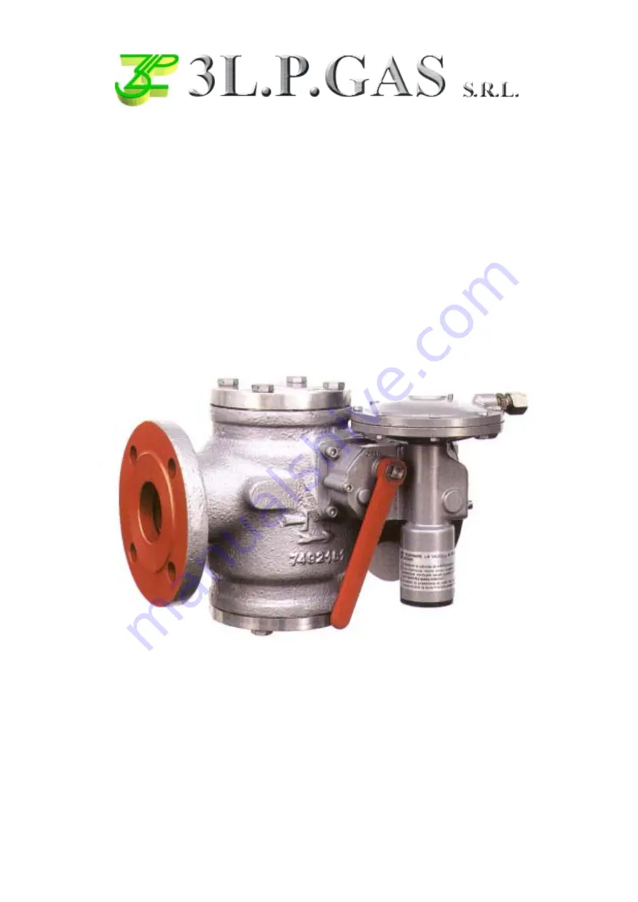
TECHNICAL MANUAL MT065
INSTALLATION, COMMISSIONING AND MAINTENANCE INSTRUCTIONS
Page 1: ...SL SL SL SL SLAM SHUT V AM SHUT V AM SHUT V AM SHUT V AM SHUT VAL AL AL AL ALVE VE VE VE VE ICN ICN ICN ICN ICN TECHNICAL MANUAL MT065 INSTALLATION COMMISSIONING AND MAINTENANCE INSTRUCTIONS ...
Page 2: ...s in the field these must be installed following the instructions of the manufacturer of the fittings themselves The choice of the fitting must be compatible with the use specified for the apparatus and with the specifications of the system when envisaged COMMISSIONING Commissioning must be carried out by adequately trained personnel During the commissioning activities the personnel not strictly n...
Page 3: ...ts on the diaphragm 21 which is integral with the shaft with cams 18 The load of the pressure Pa on the diaphragm is contrasted by the springs 14 and 15 which respectively determine intervention for a pressure increase or decrease The slam shut device is set by adjusting the rings 12 and 13 The intervention value is increased by turning the rings clockwise and vice versa when turned anticlockwise ...
Page 4: ... 5 2 6 0 0 5 1 0 0 7 9 5 2 5 1 0 7 2 N W O R B 0 4 0 5 4 0 5 6 0 5 5 0 0 3 0 5 5 0 0 3 0 0 0 2 0 0 9 0 1 5 4 6 1 0 7 2 T E L O I V 2 4 0 0 4 0 0 6 0 0 9 0 0 5 0 0 9 0 0 5 0 0 8 2 0 0 3 1 1 1 5 6 0 2 0 7 2 E R U Z A 0 5 0 5 4 0 0 6 0 0 2 1 0 5 8 0 0 2 1 0 5 8 0 0 0 5 0 0 5 2 2 1 8 3 3 0 0 7 2 E T I H W 5 3 0 5 3 1 5 7 8 5 7 0 1 9 1 5 3 2 8 3 1 7 7 3 0 0 7 2 W O L L E Y 5 1 0 5 8 0 5 0 1 0 5 5 1 0 5...
Page 5: ...ons b the piping upstream and downstream are at the same level and able to support the weight of the valve c the inlet outlet flanges of the piping are parallel d the inlet outlet flanges of the valve are clean and the valve itself has not been damaged during transport e the piping upstream has been cleaned with the removal of residual impurities such as welding slag sand paint residues water etc ...
Page 6: ...nsate in the lines of the pressure take offs a the piping itself must slope down towards the down stream connectors with a slope of about 5 10 b the connectors on the piping must always be wel ded on the top of the piping itself and there must be no burr or inward protrusion in the hole in the piping N B DO NOT PTU ON OFF VALVES ON THE IMPULSE TAKE OFFS The most common types of installation for th...
Page 7: ...EVICE which ensures the NON EXCLUSION of the main safety device and allows for its Fool proof PERIODICAL CHECKING The stem is fitted with a stroke limit pin which makes it possible to connect A and C ways only when the pin enters the check slot connect the three ways a B and C when the pin is on open 4 0 START UP 4 1 GENERAL After installation check that the inlet outlet on off valves any by pass ...
Page 8: ...valve proceed as follows Fig 9 connect a controlled auxiliary pressure to C stabilise this pressure at the notch pressing the knob 1 completely reset the slam shut device by means of the provided lever keep the knob 1 pressed a safety devices which intervene for maximum pressure slowly increase the auxiliary pressure and check the intervention value If necessary increase the intervention value by ...
Page 9: ...MANUAL ICM 3L P GAS s r l B On devices without the push valve Fig 10 we recommend connecting the control head separately to a controlled auxiliary pressure and repeating the operations described above Fig 9 Fig 10 ...
Page 10: ...e the causes which gave rise to intervention before reactivating it In the event of operating problems when personnel qualified for a specific operation are not available call the nearest service centre M E L B O R P S E S U A C E L B I S S O P Y D E M E R r o t a r u t b o t u h s m a l S e s o l c t o n s e o d d e r u t p u r 6 1 m g a r h p a i d l o r t n o C m g a r h p a i d e h t e g n a h...
Page 11: ...uipment for the first time more frequent maintenance is required because of the precarious state of cleanliness inside the piping the level of reliability required from the regulation system Before starting the disassembly operations on the apparatus you should check that a set of recommended spares is available The spares must be original 3L P GAS ones bearing in mind that the more important ones...
Page 12: ...12 3L P GAS s r l TECHNICAL MANUAL ICM 6 2 ICN SLAM SHUT VALVE MAINTENANCE PROCEDURE Fig 11 ...
Page 13: ...th the spring pos 42 and the obturator pos 10 4 Check and clean the inside of the valve body 5 Carefully check that the valve seat pos 7 is in a good state 6 Disconnect the sensing line which connects the pressure control of the slam shut to the downstream piping unscrewing the taper seal connections 7 Slacken the fixing screws pos 42 of the slam shut cover pos 17 8 Remove the slam shut cover pos ...
Page 14: ... connects the pressure control of the slam shut to the downstream piping and fix the taper seal connections 25 Put back the slam shut obturator support pos 12 along with the spring pos 42 and the obturator pos 10 26 Fit back the slam shut flange pos 14 and fix the screws pos 46 CHECKING THE TIGHTNESS AND SETTING 27 Very slowly open the on off valve upstream from the slam shut and using a foam solu...
Page 15: ...FOR ICN SLAM SHUT VALVE e p y T D N 1 d n a 1 2 d n a 1 3 d n a 2 4 6 8 A h C 3 2 9 1 3 1 8 3 2 9 1 7 1 8 3 2 9 1 7 1 8 4 2 9 1 8 2 2 9 1 8 2 2 9 1 8 B L 0 0 3 D h C 7 2 0 1 E h C 5 4 L d o C 9 9 0 9 9 9 7 M Ø 0 6 9 1 O d o C 5 4 0 9 9 9 7 7 4 0 9 9 9 7 9 4 0 9 9 9 7 ...
Page 16: ...T OF THE COMPONENTS 7 1 Tab 4 WEIGHT OF THE COMPONENTS IN KG 1 1 1 2 2 3 4 6 8 4 1 3 2 3 2 4 3 4 3 5 0 1 7 9 1 8 6 2 1 0 1 0 1 0 1 0 1 0 2 0 3 0 3 0 3 0 4 0 4 0 1 1 2 5 4 1 7 0 1 5 4 1 6 6 1 5 5 2 5 6 3 8 4 0 9 8 4 1 8 0 3 1 2 2 5 7 5 4 0 1 6 1 3 2 2 ...
Page 17: ...17 TECHNICAL MANUAL ICM 3L P GAS s r l 8 0 LIST OF RECOMMENDED SPARES ICN SLAM SHUT VALVE ...
Page 18: ...18 3L P GAS s r l TECHNICAL MANUAL ICM ...
Page 19: ... u G 1 5 8 g n i r O g n i l a e S 2 7 8 g n i r O g n i l a e S 2 1 9 g n i r O g n i l a e S 1 2 9 g n i r O g n i l a e S 1 S O P N O I T P I R C S E D S E C E I P F O R E B M U N N C I N I 8 t e k s a G 2 6 1 m g a r h p a i D 1 7 4 U g n i l a e S 1 0 5 g n i R O 1 3 5 g n i R O 1 r o f y l n O W G V D n o i s r e v S O P N O I T P I R C S E D S E C E I P F O R E B M U N N C I R T N I 8 t e k...
Page 20: ...AL ICM WHEN ORDERING SPARE PARTS PLEASE SPE CIFY Type of valve Dne nominal inlet diameter Type of head for slam shut I N I N TR Works no Serial no Year of manufacture Type of fluid used The no of the part position no Quantity desired ...
Page 21: ...ECHNICAL MANUAL ICM 3L P GAS s r l DESIGN SALE INSTALLATION OF L P G NATURAL GAS SYSTEMS Via Bologna 14 43036 FIDENZA PR ITALY Phone 0524 527766 Fax 0524 525456 http www 3lpgas com e mail 3lpgas polaris it ...