background image


CR-10 Smart Pro Enclosure Kit 

Installation Manual 1.1  

September 2022


Copyright 2022 3DUpfitters

1

Summary of Contents for CR-10 Smart Pro

Page 1: ...CR 10 Smart Pro Enclosure Kit Installation Manual 1 1 September 2022 Copyright 2022 3DUp fi tters 1 ...

Page 2: ...We forgot to put anything on this page Copyright 2022 3DUp fi tters 2 ...

Page 3: ...llation manual covers the enclosure design for the Creality CR 10 Smart Pro 3D printer If you have a di ff erent 3D printer you can fi nd the installation manual at the bottom of any product page on our website Is your Printer Customized If your printer is stock then no customization is needed If you have customized the printer you should examine any modi fi cations to ensure they don t block the ...

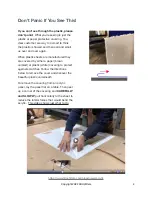
Page 4: ...d by either a paper brown colored or plastic white covering to protect against scratches Follow the directions below to remove the cover and discover the beautiful plastic underneath To remove the covering from an acrylic panel lay the panel fl at on a table Then peel up a corner of the covering and CAREFULLY and SLOWLY pull horizontally to the sheet to reduce the lateral forces that would bend th...

Page 5: ...cables and remove the enclosure fi rst Among the other things you should worry about Don t let children climb on top of the enclosure Don t use Windex or chemical cleaners Use plain water and a micro fi ber cloth Don t use a lighter on the enclosure to see if it will melt Don t use sandpaper on the acrylic Don t see how far you can bend the acrylic panels before they break Copyright 2022 3DUp fi t...

Page 6: ...ad screw The 12mm screws are long enough to attach things to the acrylic front top sides and back Each section will describe exactly which screw to use read carefully and use the speci fi ed screw for the best results Screw Tool Needed Usage Relative Size 30 50mm Hex Cap Head 3mm Hex Wrench Attach fan fi lter attach large front latch mounts 12mm Hex Cap Head 3mm Hex Wrench Connectors hinges 16mm H...

Page 7: ...he kit since they invariably end up in a drawer or land fi ll Anyone with a 3D printer should invest in a nice metric hex wrench set since many adjustments will be made along the way Finally and we can t stress this enough DON T OVERTIGHTEN THE SCREWS Leave the screws a little loose until the end adjustment phase You ll be hand tightening until the screws are snug during that process but you can e...

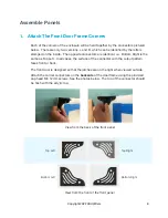
Page 8: ...p Left In all cases the surface of the connector with the cutout pattern faces front or back The front door is designed so that the latches are on the right when viewed outside Attach the corner connectors on the backside of the door frame using the provided cap head M4 12mm screws See the photos below The top of the connector should be fl ush with the acrylic top View from the back of the front p...

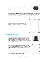
Page 9: ...n the inside of the enclosure 2 Assemble Front Door Locate the magnetic latches and use the wood screws to attach them to the latch mounts Hand tighten and make sure they re secure but do not over tighten or they may strip The latch can be later adjusted front to back to ensure the door is fl ush with the door frame Each latch mount is attached via three screws Two M4 12mm cap heads attach the lat...

Page 10: ... the front door to swing freely and fi t perfectly by fi rst placing the front on its side so that the hinges are at the top Next loosen the hinge screws and use the strike plates to hold the door in place Try to position the inside door to equal the gap on all sides and then tighten the hinge screws 3 Attach Left Side Attach the left side to the front forming an L shape that will stand up on its ...

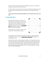
Page 11: ...inting a cover using M4 10mm screws There s a link to the cover on the product page On the top and each side are mid panel corner connectors which are simple L shapes The large 80mm hole is either for the included fan by itself an air fi lter purchased separately fan combo or it can be covered up by a plastic disk depending on how much air fl ow you want Note that the fan either by itself or paire...

Page 12: ...e screws may change depending on the depth of this particular shipment of fans If attached to the Charcoal Air Filter follow the directions included with that product At the bottom is a slit for the grommet and grommet holder The grommet is used to get the power cable and other cables into the enclosure Once the wires are through the grommet you can lift the pen o ff without unplugging anything No...

Page 13: ...the next step 6 Attach Top In general you are not going to want to place anything heavy on top of the enclosure as over time it might sag with repeated heating and cooling cycles We ve used it to hold a 1Kg roll of fi lament and had no long term problems But before you can attach the top you need to slip the support beam into the slots on the left and right sides Copyright 2022 3DUp fi tters 13 ...

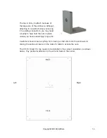
Page 14: ...lace unless you have exceedingly long arms Customers have done everything from having a child climb into the enclosure to placing the entire enclosure on the side of a table to access the nuts The CR 10 Smart Pro top needs to be installed in the correct orientation as shown below Pay particular attention to the slit and holes in the center Back Front Left Right Copyright 2022 3DUp fi tters 14 ...

Page 15: ...ith the printer to connect the fi lament sensor to its spool holder After attaching the fi lament sensor to the sensor mount attach the combined piece to the top using 2 M4 12mm hex cap screws The kit comes with an extern cable so you can plug the sensor cable into the sensor itself Copyright 2022 3DUp fi tters 15 ...

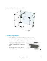
Page 16: ...nter or move it outside First detach the display from the printer and unplug the cable in the back Unfortunately the cable is just a tad short of reaching to the display outside of the enclosure so we ve included an extension cable Next attach the display holder using two M4 12mm screws Copyright 2022 3DUp fi tters 16 ...

Page 17: ...as modi fi ed to use 4 Philips head wood screws on the end of the three prongs Leave about a 2mm gap between the bottom of the screw head and the prong You can now attach the actual display to the 3 pronged display mount It can be a little tricky to sit because of the manufacturer s design but after trying it 20 times here s a good approach Copyright 2022 3DUp fi tters 17 ...

Page 18: ...ay The front tray exists to give the fans inside the printer a source of cool air With the fan in the back running this gives a clear path to bring air into the enclosure cooling the electronics and then out the back Just slide in the tray from the outside and use the M4 12mm screws to attach it to the front The lid fi ts into place covering the gap between the printer and the front of the enclosu...

Page 19: ...it tightly in the right spot 3 Re tighten the screws to hold the panel Only tighten enough to hold the pieces snuggly DO NOT OVER TIGHTEN These parts are sturdy but they re still all made of plastic Repeat the product going around the enclosure looking to make sure all panels are fl ush with each other 10 Filament The CR 10 Smart Pro printer is a direct drive and feeds fi lament through a slit in ...

Page 20: ...e has to be equal to the air moving out of the enclosure When the air moves out of the enclosure carrying volatile organic compounds it can be vented to the outside or run through an air fi lter People often ask us if the enclosures are airtight and have a bottom If your primary concern is air quality then being airtight doesn t buy you anything since the particles will fl oat out when you open th...

Page 21: ...pment and follows the manufacturer s guidelines This works great for people either interested primarily in air quality or those who are risk averse and don t want to take a chance of clogging their hot ends or decreasing the useful life of their printers More experienced 3D printer owners though for whom a clogged nozzle is a known risk might want to run the temperatures higher for less chance of ...

Page 22: ...sure combined with the particles minimal and light As you can see the fan keeps the air fl owing in and the harmful particles fl oating into the vent or fi lter 3D Printer Design Matters The other part of the equation is the printer design Those printers where the hot end is at the top of the enclosure make it easier to achieve higher temperatures because the hot air rises to the top and the verti...

Page 23: ... Temperature More Cold Air Higher Temperature Less Cold Air Pro Tip measure your current temperatures before attempting to make any changes We get support calls saying my enclosure is too hot or too cold but they didn t measure the temperature Without measurements it s impossible to tell if a printing problem is temperature related or not Copyright 2022 3DUp fi tters 23 ...

Reviews: