background image

ZPrinter

®

 150 / ZPrinter 250 User Manual

Routine Cleaning

3dscentral.3dsystems.com

36

All Rights Reserved

11/1/12

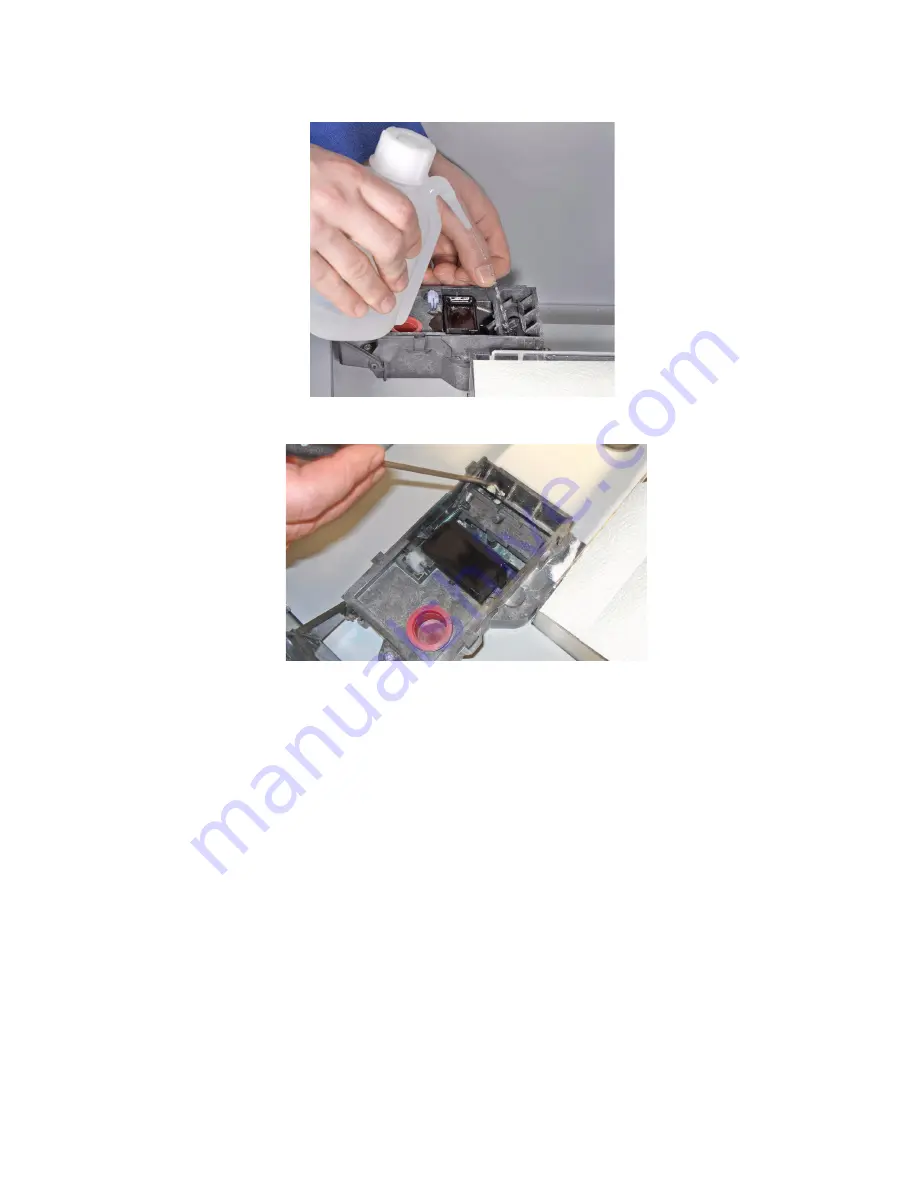
4. Position the squirt bottle close to the station and squirt water into the service station.   

5. Use the cotton swabs or a paper towel and wipe the service station thoroughly. 
6.  Use a brush or the Pick to scrape excess powder out of any corners.

7. Thoroughly wipe the Service Station clean. 
8. Wipe up any water that may have spilled onto the Deck or Build Bed. Vacuum up any loose powder. 

Do not vacuum the service station itself.

Important

: Never vacuum up water or other fluids - it will clog the vacuum system.

9. Remove the paper towels from the front overflow. Close the printer top cover.

3.5  Clean the Parking Caps (ZPrinter 250 Type 1 only)

The Parking Caps provide a clean, smooth surface for seating the print heads between builds. This helps 
prevent the print heads from drying out.

Note: 

Parking caps are only installed on older ZPrinter 250 printers (Type 1). There are no parking caps on 

newer ZPrinter 250 printers (Type 3) and on all ZPrinter 150 printers.

Before you begin:

Get several dry paper towels

Get the squirt bottle included in your Accessories Kit

Fill the squirt bottle with distilled water

1. Lift the Parking Cap cover to a horizontal position and place a dry paper towel underneath.
2. Squirt the distilled water onto the cover to clean the Parking Caps. Do not squirt water into the powder.

Summary of Contents for ZPRINTER 150

Page 1: ...11 1 12 All Rights Reserved ZPrinter 150 ZPrinter 250 User Manual Part Number 95008 Rev C ...

Page 2: ...pose whatsoever other than what is required to install and use this ZPrinter system Use of Equipment 3D Systems Equipment and use of the Equipment may be subject to limitations imposed under patents licensed to or owned by 3D Systems and is to be used solely for the fabrication of appearance models and prototypes using new 3D Systems supplied consumables from 3D Systems or its authorized distribut...

Page 3: ...SS PROFITS OR BUSINESS INTERRUPTION ARISING OUT OF THE USE OR INABILITY TO USE PRODUCTS OR SER VICES SOLD HEREUNDER IN NO EVENT WILL THE COMPANY S LIABILITY EXCEED THE TOTAL CHARGE OF THIS ZPRINTER SYSTEM WARRANTY PERIOD In the U S warranty is for 90 days and covers service parts and training material In the EU warranty is for 1 year and covers service parts and training material FULL WARRANTY STA...

Page 4: ...arriage and Print Head 13 1 6 7 Pogo Pins and Septum 14 1 6 8 LCD Display And Control Knob Control Panel 15 1 6 9 Control Knob Operations 15 1 7 LCD Menu Overview ZPrinter 150 16 1 8 LCD Menu Overview ZPrinter 250 16 1 9 Where To Go For More Information 16 2 Setup And Print The Build 17 2 1 Install ZPrint and ZEdit 17 2 1 1 ZPrint 17 2 1 2 ZEdit 17 2 2 Choose Part Orientation 17 2 2 1 Speed Streng...

Page 5: ... Processing Using Water Cure 38 4 1 1 Description 38 4 1 2 Spraying vs Dipping 38 4 1 3 Handling and Usage Information 38 4 1 4 Set Up the Work Area 38 4 1 5 Spraying method 38 4 1 6 Dipping method 40 4 2 Post Processing With Z Bond 41 4 2 1 Preparation 41 4 2 2 Post Processing Using the Dipping Method 42 4 2 3 Post Processing Using the Drizzle Method 42 5 Additional Operations 44 5 1 The Printer ...

Page 6: ... Errors Slow Axis 69 7 5 1 Troubleshoot Slow Axis 70 7 6 Network Errors Cannot Connect to Printer 71 7 7 Network Errors Packet Timeout 72 7 8 Part Quality Issues Streaky Striped Parts Delamination Weak Parts 73 7 9 Part Quality Issues Bad Surface Finish 74 7 9 1 Bad Horizontal Surface Finish 74 7 9 2 Bad Vertical Surface Finish 74 7 10 Miscellaneous Problems 75 7 10 1 Vacuum Has Low No Suction 75 ...

Page 7: ...d techniques on our 3DP User Web site at 3dscentral 3dsystems com This Web site is tailored to both beginner and advanced customers We recommend that you register immediately to receive free unlimited access to this excellent resource This Section will cover the following topics Section 1 1 Key Features Section 1 2 Specifications Section 1 3 Computer System Requirements Section 1 4 How 3D Printing...

Page 8: ... 100 10 Base T Operating Environment Ambient Temperatures Ambient Relative Humidity Maximum Temp Range 50 85 F 10 29 4 C Recommended Temp Range 55 80 F 12 7 26 6 C Maximum RH Range 15 70 non condensing Recommended RH Range 20 60 non condensing May experience sub optimal printing performance at environmental extremes Build Volume 7 3 x 9 3 x 5 185 x 236 x 132 mm 340 cubic inches build capacity Buil...

Page 9: ...n our 3DS Central Web site in the Support section 3dscentral 3dsystems com Note that ZPrint ZEdit and ZEdit Pro are 32 bit applications and when used on a 64 bit computer will operate in 32 bit mode Materials High Performance Composite zp 150 Powder with zb 63 Binder 3D Systems is always evaluating new materials for use with your printer For the latest information check the Materials section of ou...

Page 10: ...layers that are between 0 0035 0 004 0 089 0 102 mm thick Before printing ZPrint evaluates the part geometry and checks if there are enough materials in the printer to print the number of layers required to build the part If there are the printer then prints each layer one after the other from the bottom of the part to the top If not ZPrint will prompt you to add powder to add binder or to change ...

Page 11: ... and its Pogo Pin Connectors Consumables Powder Binder Infiltrant products that are available in a variety of systems for all of your modeling needs All consumables have been developed for the fastest printing speeds and lowest materi als costs Debris Separator Located in the Build Chamber Its function is to prevent chunks or particles from going back into the printer Feeder during any vacuuming o...

Page 12: ...tact points on a print head cartridge that match up with the Pogo Pins Purge Process of removing ink from the HP11 print head to prepare it for dispensing binder Service Station Cleans the print head jets to remove powder residue during printing It is extremely important to clean the Service Station after every build to remove residue buildup that gets left on the Ser vice Station during a build I...

Page 13: ...ss speci fied other wise all components are the same on the two printers This manual applies to all ZPrinter and ZPrinter 250 systems Older units are called Type 1 and the new est versions are called Type 3 The Types are nearly identical and any differences are called out in the pictures that follow Type 3 printers have Type 3 printed on their serial number plates 1 6 1 System Exterior Number Comp...

Page 14: ...ZPrinter 150 ZPrinter 250 User Manual ZPrinter 150 ZPrinter 250 Overview 3dscentral 3dsystems com 8 All Rights Reserved 11 1 12 1 6 2 Build Chamber Interior ...

Page 15: ...ights Reserved 11 1 12 Number Component 1 Binder Cartridge 2 Debris Separator 3 Vacuum Hose 4 Service Station 5 Deck 6 Fast Axis Assembly 7 Build Bed 8 Front Overflow 9 Parking Caps Behind Fast Axis in top photo ZPrinter 250 Type 1 only filled with blank plate on ZPrinter 250 Type 3 and on all ZPrinter 150 ...

Page 16: ...systems com 10 All Rights Reserved 11 1 12 1 6 3 ZPrinter 150 ZPrinter 250 Rear View Number Component 1 Upper Rear Panel Full length rear panel on Type 3 2 Lower Rear Panel Not present on Type 3 3 Vacuum Port External Depowder 4 Air Vents 5 Nameplate Serial Number 6 Electronics Box E Box ...

Page 17: ...eserved 11 1 12 1 6 4 ZPrinter 150 ZPrinter 250 Rear View Connections Number Component 1 Power Switch 2 Power Cord Connection 3 Network Cable Connection Ethernet RJ 45 4 Electronics Box E Box Connections ZPrinter 150 250 Type 1 only not present on ZPrinter 150 250 Type 3 5 Diagnostic LEDs Type 3 only Type 1 Type 3 ...

Page 18: ...er 250 User Manual ZPrinter 150 ZPrinter 250 Overview 3dscentral 3dsystems com 12 All Rights Reserved 11 1 12 1 6 5 Service Station Number Component 1 Cover 2 Wick 3 Squeegees 4 Fill Cap Cleaning Solution 5 Front Overflow ...

Page 19: ...250 Overview 3dscentral 3dsystems com 13 All Rights Reserved 11 1 12 1 6 6 Carriage and Print Head Number Component 1 Cover 2 Print Head HP 11 3 Carriage Plug ZPrinter 150 only Color Print Head HP 57 ZPrinter 250 only 4 Printhead Tubing ZPrinter 150 ZPrinter 250 ...

Page 20: ... 150 ZPrinter 250 Overview 3dscentral 3dsystems com 14 All Rights Reserved 11 1 12 1 6 7 Pogo Pins and Septum Number Component 1 Pogo Pins Binder Printhead HP 11 2 Septum 3 Pogo Pins Color Printhead HP 57 ZPrinter 250 only ZPrinter 150 ZPrinter 250 ...

Page 21: ...rved 11 1 12 1 6 8 LCD Display And Control Knob Control Panel 1 6 9 Control Knob Operations Push the Control Knob once to Bring up the LCD menu Select a menu item Open a submenu Start Cancel Stop a menu function Turn the Control Knob left or right to Highlight a menu item Number Component 1 LCD Display 2 Control Knob ...

Page 22: ...ser Web site regarding 3D applications and printing post processing techniques Post Processing Learn more about the different post processing products that are available to use with your printer on the Materials section of our User Web site at 3dscentral 3dsystems com Consumables To order consumables materials visit 3DS Shop at 3dsshop 3dsystems com If you are an international customer you can ord...

Page 23: ...u use the version of ZPrint that came with the ZPrinter 150 ZPrinter 250 If you encounter any problems during installation please contact your local Service Provider or Reseller or visit the Support section of our Web site at 3dscentral 3dsystems com 2 1 2 ZEdit ZEdit is an add on software that ships with ZPrint This software program works in conjunction with ZPrint to apply labels to your part as...

Page 24: ... bands across the X or the slow axis the fast axis direction of travel and in laminated layers along the Z Axis Once a part is infiltrated it uniformly takes on the strength characteristics of the infiltrating product Accuracy The accuracy of your part depends on how clean the printer is your printer powder set tings and the materials you choose for post processing You can also employ features lik...

Page 25: ... bottom most surface of the part without actually touching the part and the bottom of the Build Bed Generate a Fixture under a part or a portion of a part to create a cradle that is easily handled during transport depowdering and post processing An optional bumper feature is available to provide additional protection for especially delicate parts or multiple parts in the same build For details on ...

Page 26: ...ext The file is opened in a new ZPrint window using the units specified in this dialog 4 If you would like to add additional files to the build select File Import and select more files By default ZPrint will position each file in the Build Bed for the fastest print time 2 3 1 ZPrint Main Window After the file is opened the part will be displayed on the ZPrint Main Window Here it will be shown in a...

Page 27: ...y the Default Printer Settings dialog 2 In the Default Printer Settings dialog check that the default printer is the printer that is connected to your computer If it is not click Select Printer and proceed with Step 3 If it is click Cancel and skip the rest of this procedure 3 In the Select 3D Printer dialog choose Network as the Port Type Click the Find button to locate the printer on the network...

Page 28: ...ings dialog 2 Select the printer and the powder type from the left side panel to view the settings for that combination ZPrint defaults to the recommended powder settings for the Saturation Levels Binder Volume Ratio Anisotropic Scaling and Fixture Clearance Important Most of the powder settings cannot be changed but you can override the settings for the Layer Thickness Bleed Compensation Anisotro...

Page 29: ... is toggled on the ZPrint 3D View menu when you select the Switch Layer View 3D View command or by selecting the 2D icon on the Toolbar When printing single or multiple parts slice viewing allows you to view the cross sections of the part s to identify any errors in the file Collision Detection is located on the ZPrint View menu When printing multiple parts or a part with a Fixture always run Coll...

Page 30: ...formation contained in your 3D model and print a completely white monochrome part ZPrinter 250 only 5 Click OK 2 7 Prepare the Build Area Go to your printer and check each item listed below to ensure the printer is ready to print It is important to check each of these items before every build Check that the Deck Fast Axis and Build Bed are clean of any powder See Section 3 1 Vac uum Excess Powder ...

Page 31: ...be what happened during the print job These are very useful in troubleshooting printing problems and we recommend you leave them checked 2 Select OK when you have selected your options 3 The Printer Status dialog appears ZPrint checks the printer readiness and calculates the materials needed to complete the build The results are reported in the Printer Status dialog for you to check before startin...

Page 32: ...in the Print Head Powder and General sections show OK the Print button is enabled Click Print to start the build Before starting the build the printer will Service the print head Fill the Build Bed with powder and then spread one layer to make the top surface smooth 7 The Printing dialog opens and tracks the following information for the duration of the build Estimated Finish Time Estimated Time R...

Page 33: ... LCD menu will count down the time remaining to dry the part Drying the part gives it added strength so you should not handle parts before they have adequately dried You can leave the part in the Build Bed after the drying cycle ends and it will continue to increase in strength The longer a part is dried the stronger it becomes although until it is infiltrated it will still be frag ile and should ...

Page 34: ...ed back into the printer Feeder so it can be used for future builds Important For delicate parts or parts with especially delicate features it is recommended that you build the part with a Fixture Refer to the ZPrint User Manual for details on adding a Fixture 2 10 2 Fine Powder Removal After the bulk of the powder is removed from the Build Bed gently pick up the part and place it in the Pow der R...

Page 35: ...the top of the Build Box exposing the Build Plate and the foam behind it 5 Gently lift the Build Plate and the part and place it in the Powder Recycling Station 6 When you have depowdered your part and removed it from the Build Plate clean any remaining pow der off the Build Plate 7 Thoroughly clean the underside of the Build Plate to remove any powder from the holes that mate with the Locating Pi...

Page 36: ...the printer Regular cleaning and maintenance is the simplest best way to ensure your parts look their best and to keep your printer running trouble free See Section 3 Routine Cleaning for complete details on how to perform these routine cleaning tasks After you have cleaned and prepared the printer for the next build proceed with the Post Processing steps in Section 4 Post Processing With Z Bond N...

Page 37: ...r 2 Select VACUUM on the LCD menu 3 Open the printer top cover The vacuum starts Remove the vacuum hose from its stand 4 Vacuum any excess powder in the Build Bed around the Deck and on top of the Fast Axis Pull the Fast Axis forward and check for powder towards the back of the Build Chamber as well You can leave powder in the Spread Deck the area behind the Build Bed where powder is depos ited fr...

Page 38: ... be disabled 7 When you are finished return the hose to its holder Important Never vacuum up water or other fluids it will clog the vacuum system 3 2 Empty The Debris Separator After vacuuming empty the Debris Separator The Debris Separator catches any large particles and keeps those pieces from being recycled into the feeder To empty the Debris Separator follow the steps below 1 Pull the Debris S...

Page 39: ... towels under the Fast Axis 3 Using a paper towel dampened with distilled water wipe the top and bottom Rails to remove any pow der Move the Carriage back and forth as needed to clean the entire length of both rails 4 Dry both Rails thoroughly with a clean dry paper towel 5 Using a fresh paper towel wipe the Carriage to remove any powder 6 Wipe or vacuum the Build Bed and Deck as needed to remove ...

Page 40: ...ead during printing Clean the Service Station after every build to remove residue buildup and ensure the print head is kept clean Before you begin Get several dry paper towels and some cotton swabs Get the squirt bottle filled with distilled water Wear disposable gloves Get the Pick from the Accessories Kit 3 4 1 Example Dirty Service Station Number Description 1 Powder Residue 2 Ink Binder Residu...

Page 41: ...ights Reserved 11 1 12 3 4 2 Example Clean Service Station 3 4 3 Cleaning Procedure 1 Place paper towels around the Service Station and between the Service Station and the Build Bed 2 Cover the front overflow with paper towels 3 Push the lever to position the Squeegees for easier cleaning ...

Page 42: ...acuum system 9 Remove the paper towels from the front overflow Close the printer top cover 3 5 Clean the Parking Caps ZPrinter 250 Type 1 only The Parking Caps provide a clean smooth surface for seating the print heads between builds This helps prevent the print heads from drying out Note Parking caps are only installed on older ZPrinter 250 printers Type 1 There are no parking caps on newer ZPrin...

Page 43: ...rinter 250 User Manual Routine Cleaning 3dscentral 3dsystems com 37 All Rights Reserved 11 1 12 3 Use a dry paper towel to wipe the Parking Caps clean 4 Remove the paper towel and wipe up any excess water on the Deck ...

Page 44: ...e added strength In cases where complete penetration of thick sections is desired the dipping method should be used 4 1 3 Handling and Usage Information The salt used in this procedure must be magnesium sulfate heptahydrate In most countries this is sold as Epsom Salt Do NOT use any other type of salt For storage handling precautions of the dry salt refer to the Epsom Salt package or consult your ...

Page 45: ...mount of salt mixed in is incorrect the salt solution may be too dilute and parts may become weak during spraying Spray the Part 1 Place your part on a flat surface coated with paper towels or wax paper Tip Spread extra towels or paper around the area to catch any overspray This will make cleanup easier Overspray can be wiped up with a damp sponge or cloth 2 Lightly coat one side of your part with...

Page 46: ...may be too dilute and parts may become weak during spraying Tip Using warm water helps the salt dissolve faster 4 Stir the water solution intermittently until the salt completely dissolves 5 10 minutes If there are any undissolved crystals at the bottom allow 1 2 hours to dissolve and then stir again for 1 2 minutes Note Failure to dissolve all the salt could cause crystals to deposit onto your pa...

Page 47: ...processing materials techniques Best Practices and material storage guidelines All this information plus shop ping for consumables is at 3dscentral 3dsystems com Safety Precautions Read and understand the Material Safety Data Sheet before using or handling this product Wear a lab coat or smock gloves face shield or goggles Apply in a well ventilated area Specialized containers are recommended for ...

Page 48: ...aper near the container and pour enough Z Bond into the container to completely submerge the part 2 Gently submerge your part into the liquid 3 Look for bubbles rising If you don t see any let the part sit submerged for about 10 seconds and then remove it from the liquid 4 If you see bubbles rising wait until the bubbles stop and then remove the part 5 Keep the part moving in your hands so it does...

Page 49: ... delicate areas first Wet as much of the part as you can easily reach 4 Reposition the part and repeat this process until the entire part is infiltrated 5 Quickly and thoroughly wipe any excess liquid off the part with the paper towels and place the part on the wax paper 6 Do not let excess liquid pool on the part as this may cause its texture to change 7 Move the part frequently for the first few...

Page 50: ...ection 5 2 The Printer Status Dialog Section 5 3 Change Print Head Section 5 4 Add Binder Section 5 5 Add Powder Section 5 6 Add Wash Fluid Section 5 7 Replace the Waste Tray Section 5 8 Position Build Piston Build Bed 5 1 The Printer Status Report The printer has an onboard Status Report you can use to check powder levels head life remaining etc This is especially useful if the printer is located...

Page 51: ...r Status dialog shows the printer is ready for printing Notice that each item shows OK and the Print button is enabled From here you would choose your printing options and click Print to start the job Before the printer starts printing your file it will first fill the Build Bed with powder spread a layer to ensure the Build Bed surface is smooth service the print head ...

Page 52: ... Print If there are not enough materials to complete the job or the printer is not properly prepared a mes sage appears similar to the examples in red above When any one of these messages appears the Print button is disabled The remainder of this chapter describes how to clear a message in the Printer Status dialog and start the build ...

Page 53: ...EAD then CHANGE PRINT HEAD The Printer moves the Fast Axis out over the Build Bed 3 If the piston is not already lowered some distance into the build box lower it now by selecting LOWER PISTON The piston will lower a short distance To lower it further select LOWER PISTON again 4 Open the carriage cover by releasing the latch 5 Lift print head out of its slot and properly recycle or dispose of the ...

Page 54: ...m 48 All Rights Reserved 11 1 12 6 Get an alcohol swab included with your Startup Kit Snap it to break the glass inside and squeeze the tube to saturate the swab 7 Wipe off all the pogo pins for both printhead s inside the carriage with the alcohol swab Use addi tional swabs if needed ...

Page 55: ...Rights Reserved 11 1 12 8 Wet a paper towel with distilled water and wipe the underside of the Carriage Keep wiping until the towel picks up no more debris or ink 9 Dry with a clean paper towel 10 Remove the new printhead from its packaging Be sure to pull the tape tab off of the new printhead ...

Page 56: ...12 On a ZPrinter 250 also insert the other printhead that is not being replaced 13 Close the carriage cover by pressing down until you hear it click shut Be sure the latch is engaged 14 Close the printer top cover Select CONTINUE on the LCD 15 The fast axis reparks 16 If the HP11 printhead was replaced it will need to be purged of its black ink before printing a part You can select PURGE now other...

Page 57: ...e ZPrint Printer Status dialog To add binder follow the steps below 1 Pull the empty binder cartridge out of its housing on the printer 2 Get a new binder cartridge Check the expiration date and check the cartridge label for the correct ori entation 3 Insert the cartridge into its housing Ensure the cartridge is pushed all the way in You should feel it gently snap into place Important If a cartrid...

Page 58: ...d all powder out of the Build Bed and from the Deck Fast Axis etc Finished depowdering any parts in the Fine Powder Removal Chamber Vacuumed up any other powder needing cleanup Refer to the steps in Section 3 1 Vacuum Excess Powder and Section 2 10 Depowder the Part 2 Before unsealing the powder canister turn it upside down and shake to loosen the powder inside 3 Check the expiration date on the c...

Page 59: ...ical capacity of the Build Bed Adding further powder provides no benefit and risks overfilling the feeder Do not continue running the vacuum after the Feeder is Full message appears If you continue to vac uum powder into the feeder the LCD will display FEEDER POWDER LIMIT and the vacuum will be disabled 8 Remove the powder canister and return the vacuum hose to its stand 5 6 Add Wash Fluid To add ...

Page 60: ... cover 2 Pull the full Waste Tray out of its compartment on the printer 3 Insert a new Waste Tray into its compartment Ensure the Tray is pushed all the way in 4 Replace the rear bottom panel 5 8 Position Build Piston Build Bed The Build Bed platform must be in its proper position at the top of the Build Bed in order for the printer to fill the bed and spread a layer of powder before starting a pr...

Page 61: ...ing the Slow Axis bearing and the Piston Screw require lubrication ZPrint will prompt you when lubrica tion of any of these components is required Only lubricate these components when you are prompted to in ZPrint While lubrication of these items is important it is equally important not to over grease the bearings and pis ton screw when lubricating Only a very small amount of grease is required to...

Page 62: ... Carriage 8 Reset the Maintenance Counter in ZPrint 6 3 Piston Screw Lubrication Frequency When prompted to in ZPrint 1 Remove both the upper and lower rear cover panels of the printer 2 Remove the left Build Chamber side panel 3 On the LCD display select BUILD CHAMBER LOWER PLATFORM Hold the Control Knob down and lower the Build Bed platform as far as you can to expose the entire length of the pi...

Page 63: ...gth of the screw 8 Move the Build Bed up and down through its full range of travel a couple of times to finish lubricating the screw Use the LCD menu items BUILD CHAMBER RAISE PLATFORM and BUILD CHAMBER LOWER PLATFORM Don t forget to hold down the Control Knob to raise or lower the platform 9 Wipe off any grease that may collect at the bottom of the screw with a clean paper towel 10 Replace the si...

Page 64: ...that is part of your Accessories Kit according to the instructions found in the document 09576 Grease Gun Loading Instructions which is supplied in the materials that were shipped with the printer You can also find these instructions on our Web site at 3dscentral 3dsystems com 5 Squeeze the handle until grease dispenses from the tip Wipe clean with a clean paper towel 6 Place the tip of the grease...

Page 65: ...ove the Fast Axis out over the build bed 3 On the LCD select BUILD CHAMBER then CONTROL ROLLER 4 On the LCD select ROLLER ON OFF to turn the Spreader Roller on 5 Using a paper towel dampened with distilled water clean the Spreader Roller thoroughly by reaching up from underneath 6 Dry the roller thoroughly with a clean dry paper towel 7 On the LCD select ROLLER ON OFF to turn the Spreader Roller o...

Page 66: ...er or by 3D Systems Service 1 Open ZPrint and select the printer you will be upgrading Make sure the printer is powered up and online 2 In ZPrint select Service Check Status to see which version of Firmware is installed on your printer 3 If you need to upload Firmware do the following Go to 3DS Central and find your printer in the Products section Then on your printer s page click on Firmware and ...

Page 67: ...LCD to display ONLINE before continuing 6 After rebooting in ZPrint select Service Check Status Verify that the new firmware version number is listed 6 7 Printer Storage Preparation The ZPrinter 150 ZPrinter 250 should never be turned off so it can automatically service the print head and exercise the moving components during idle times If the printer will be unused for an extended period several ...

Page 68: ...es it report any errors What are the error codes Are there problems with the parts it builds What specifically is wrong with the parts Troubleshoot Once you have the information above use these troubleshooting flowcharts and tables to isolate the prob lem Power Up Problems Section 7 2 Problems Powering Up Print Head Errors Section 7 3 Print Head Errors Weak Parts Motion Errors Section 7 4 Motion E...

Page 69: ...y needed maintenance Check the Printer Status Dialog window in ZPrint for any maintenance that is due Section 5 2 The Printer Status Dialog 3 Inspect the printer Perform a quick inspection of the machine During the inspection you should be looking for any signs of leaks loose screws or loose nuts Loose screws or nuts should be tightened and leaks should be reported to your local Service Provider i...

Page 70: ...User Manual Troubleshooting the ZPrinter 150 ZPrinter 250 3dscentral 3dsystems com 64 All Rights Reserved 11 1 12 7 2 Problems Powering Up If your printer does not power up normally use the flowchart below to isolate the problem ...

Page 71: ...Head Error Error 40800 x Head Error Error 40801 Headcard Power Fail Error 40802 x Use Only HP11 Error 60700 Head X temperature calibration failed Error 60701 Head X invalid serial number Error 60702 Head X temperature too high Error 10040 Pogo Comm Error For more detailed information on what these errors mean see Section 7 11 Error Codes and Messages Background Details 7 3 1 Try This First Most of...

Page 72: ...roubleshoot Print Head Weak Parts If your printer is reporting print head errors or is building parts that break too easily follow the flowchart below Also see Section 7 8 Part Quality Issues Streaky Striped Parts Delamination Weak Parts How to do it To remove the printhead and clean the pogo pins follow the steps in Section 5 3 Change Print Head ...

Page 73: ...at all relate to the Fast Axis and that all share a common set of solutions Error Codes covered in this section Error 2301 1 Motors Not Rezeroed Error 2303 1x Axis Pos Error Error 2305 1x Axis Settle Error 2400 1x Axis Seek Error Error 3011 System Error Error 3013 Sequencer Timeout Error 43000 Sequencer Timeout For more detailed information on what these errors mean see Section 7 11 Error Codes an...

Page 74: ...68 All Rights Reserved 11 1 12 7 4 1 Troubleshoot Fast Axis If your printer is reporting Fast Axis errors follow the flowchart below How to do it To perform the cleaning and lubrication called for in the flowchart see Section 3 3 Clean The Fast Axis Rails and Carriage Section 6 2 Fast Axis Bearing Lubrication ...

Page 75: ...lutions Error Codes covered in this section Error 2301 0 Motors Not Rezeroed Error 2303 0 x Axis Pos Error Error 2305 0 x Axis Settle Error Error 2400 0 x Axis Seek Error Error 3011 System Error Error 3013 Sequencer Timeout Error 43000 Sequencer Timeout For more detailed information on what these errors mean see Section 7 11 Error Codes and Messages Background Details How to do it To perform the c...

Page 76: ...r 250 User Manual Troubleshooting the ZPrinter 150 ZPrinter 250 3dscentral 3dsystems com 70 All Rights Reserved 11 1 12 7 5 1 Troubleshoot Slow Axis If your printer is reporting Slow Axis errors follow the flowchart below ...

Page 77: ...shooting the ZPrinter 150 ZPrinter 250 3dscentral 3dsystems com 71 All Rights Reserved 11 1 12 7 6 Network Errors Cannot Connect to Printer If you have trouble connecting to your printer over the network follow the troubleshooting flowchart below ...

Page 78: ...file data fast enough For example some files may be layer data heavy meaning that the bulk of the data is in a small quantity of layers Solution Check for these problems The PC used to control the printer may Be too busy running other applications Be running a virus or spyware scan Be in a sleep or suspend mode due to power management settings Not meet the minimum system requirements See the minim...

Page 79: ...minate Delamination layers splitting apart may be due to a print head that is caked with powder or a pause in network communications Solution Both Clean the service station See Ensure the printer has cleaning solution Clean the Fast Axis Rails of any debris and reboot the printer See Section 3 3 Clean The Fast Axis Rails and Carriage If the problem persists Clean the pogo pins and the print head c...

Page 80: ...xplanation A bad surface finish on horizontal surfaces is usually the result of debris buildup on the Spreader Roller The debris sticks to the Roller and prevents it from spreading a smooth flat layer of powder See the photo below color part shown to highlight the problem Solution Clean the Spreader Roller See Section 6 5 Clean The Spreader Roller 7 9 2 Bad Vertical Surface Finish Explanation A ba...

Page 81: ...ptied and cleaned or that the vacuum hose is plugged or damaged Less commonly the printer may have been turned off and on too quickly Always wait 1 minute after turning power off before turning it on again Solution Debris Separator Remove the Debris Separator and empty the contents into a waste receptacle Check that its gasket is not damaged Also check that all four magnets are in place on the bac...

Page 82: ...rvice Provider 7 10 2 Binder Cartridge is Full But ZPrint Indicates Empty Explanation This is usually caused by a damaged binder cartridge or a failure in the binder cartridge pocket Solution Remove and reseat the binder cartridge Check the following Be sure it s the correct cartridge for that pocket Check the label to be sure it s oriented correctly Snap it fully into place in the pocket If that ...

Page 83: ...int head reaching the end of its life As a print head ages it overheats and eventually reports this error It could also be a failed connection between the printer and the print head Solution This error is most often avoided by following best prac tices for keeping the printer clear of excess powder and to clean the pogo contacts every time a print head is changed The ZPrinter 150 ZPrinter 250 will...

Page 84: ...ips on maintaining your printer troubleshooting problems or to contact our Service staff 3dscentral 3dsystems com Error 1905 Explanation This error is caused by a layer that is too large for the printer s buffer The printer is unable to process the layer and reports the error This is most common with GIS architecture and scanned files which are usually very large Solution Try rotating the part on ...

Page 85: ... Description of Problem Also look at the back of the printer near where the power cord attaches If you have a ZPrinter 150 250 Type 3 there will be 4 diagnostic LEDs Record the pattern of which LEDs are illuminated and which are not and report this to Service 7 14 Contact 3D Systems If you have any questions about your 3D ZPrinter or the ZPrint ZEdit Software please contact your local Reseller Ser...

Page 86: ...perations 15 Cover Close 54 CSA CE Approval 2 Cylindrical features 19 Cylindrical Features Parts with 19 D Debris Filter Definition 5 Debris Filter Empty 32 Deck Definition 5 Default Powder Settings 22 Default Printer Settings 21 Default Settings Check or Change 21 Depowder Definition 5 Diagram of interior and exterior saturation 4 Diagram Carriage 13 Diagram Print Heads 13 Diagram Rear View 10 11...

Page 87: ...6 Platform Definition 5 Pogo Pins Definition 5 Powder Removal Automatic 28 Powder Removal Fine 28 Powder Screen Definition 6 Powder Settings Defaults 22 Powder Type Create New 23 Powder Add To Feeder 52 Powder Definition 5 Power Requirements 2 Power Up Problems 64 Prep Build Chamber 54 Prepare Build Area 24 Print Head Contacts Definition 6 Print Head Errors 65 Print Head s Change 47 Print Head Def...

Page 88: ...aring Lubrication 58 Specifications 2 Speed Build 2 Speed Printing 17 Storage Preparation Printer 61 Strength 17 Strength Part 17 T Terms 5 Troubleshooting 62 V Vacuum Has Low No Suction 75 Vacuum Powder 31 Volume Build 2 W Waste System 3 Waste Tray Definition 5 Weak Parts 65 Weight Printer 2 Z ZPrint Main Window 20 ZPrint Maintenance Dialog 55 ZPrint ZEdit Installation 17 ZPrinter 650 Overview 1 ...

Reviews: