background image

3

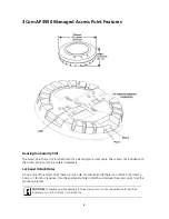
RJ-45 Cable Ports

The access point has two RJ-45 ports. Each port provides a 10/100/1000BASE-TX Ethernet connection to 
a WX controller. The connection can be direct to an WX controller or indirect through an intermediate 
Layer 2 or Layer 3 network. For best performance, it is not recommend that the AP 3950 be connected 
directly to the WXR100 or WX1200 wireless controller as these controllers only have 10/100 ports.

The access point receives power and data through the RJ-45 ports. Use a Category 5 (Cat 5) cable with 
straight-through signaling and standard RJ-45 connectors to connect an access point to a controller in 
the network. 

The two RJ-45 ports support dual-homed configurations for redundancy. The access point uses only one 
link for booting, configuration, and data transfer. If the link becomes unavailable, the access point can 
reboot using the other link. This second port can also be used for supplying additional power.   Since the 
AP 3950 is a dual radio 802.11a/b/g/n access point, its power draw is slightly greater than what 802.3af 
power can supply.   When only a single 802.3af power connection is applied, the AP uses two 
transmitters rather than all three (i.e. 2 x 3 MIMO).  When dual 802.3af ports are used, the AP comes up 
in full 3 x 3 MIMO mode for extended ranges.  You can also power the AP via a single 802.3af+, also 
known as pre-802.3at, switch or injector to get full 3 x 3 MIMO mode.

The ports are identical except for logical numbering (1 or 2). You can use either port to connect the 
access point to a WX controller. However, the access point always attempts to boot on port 1 first. Only 
if the boot attempt on port 1 fails does the access point attempt to boot on port 2. If one port becomes 
unavailable, the other port can provide full power to the access point.

Observing Safety Precautions

This equipment must be installed in compliance with local and national building codes, regulatory 
restrictions, and FCC rules. For the safety of people and equipment, only professional network personnel 
should install the access point

.\

Note:

 The access point does not support daisy-chain configurations. Do not connect the access point 

to another AP3950 access point.

WARNING:


 To comply with FCC radio frequency (RF) exposure limits, a minimum body-to-

antenna distance of 20 cm (8 inches) must be maintained when the access point is operational.

WARNING:

  To avoid possible injury or damage to equipment, you must use power supply equipment 

that is safety certified according to UL, CSA, IEC, or other applicable national or international safety 
requirements for the country of use. All references to power supply in this document refer to equipment 
meeting these requirements.

WARNING:


 Do not operate the access point near unshielded blasting caps or in an otherwise 

explosive environment unless the device has been modified for such use by qualified personnel.

WARNING:

  Do not touch or move the access point when the antennas are transmitting or receiving.

WARNING:


 Do not hold any radio device so that the antenna is very close to or touching the face, 

eyes, or other exposed body part while the device’s radio antenna is transmitting.

Summary of Contents for 3CRWX395075A - Wireless LAN Managed Access Point...

Page 1: ...WXR100 Power is supplied via Power Over Ethernet PoE Since the throughput of the AP 3950 is greater than 100Mb s it is recommended that the AP 3950 be connected to a Gigabit Ethernet port The followin...

Page 2: ...be ordered separately Lock and Unlock Holes On one side of the access point there is a lock hole On the other side there is an unlock hole Insert a 3 mm or 1 8 inch screwdriver into the appropriate ho...

Page 3: ...ou can use either port to connect the access point to a WX controller However the access point always attempts to boot on port 1 first Only if the boot attempt on port 1 fails does the access point at...

Page 4: ...revent the cable from being routed through the mounting bracket Power Power must be supplied via an 802 3af Power Over Ethernet PoE compliant device Removal of the Ethernet cable is the only method of...

Page 5: ...MAC address is printed on the back of the access point Additional MAC address labels are shipped with the access point 3 Mounting the Access Point The access point can be mounted on the following typ...

Page 6: ...nstead Suspended Ceiling Flush Ceiling Tiles This procedure applies to T bars that are 23 9 mm 15 16 inches wide For a 14 2 mm 9 16 inch or 15 9 mm 5 8 inch T bar go to Suspended Ceiling Installation...

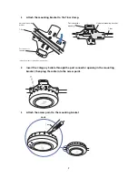
Page 7: ...unting bracket then plug the cable into the access point 5 Attach the access point to the mounting bracket T bar Viewed from above ceiling tiles looking down 840 9502 0005 Universal mounting bracket P...

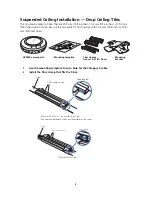
Page 8: ...ut a hole for the Category 5 cable 2 Install the T bar clamp that fits the T bar T bar clamps use set that fits T bar Mounting template Mounting bracket Mobility point TM AP3950 access point Mounting...

Page 9: ...the port connector opening in the mounting bracket then plug the cable into the access point 840 9502 0011 840 9502 0008 T bar T bar clamps attached to T bar Universal mounting bracket 840 9502 0012...

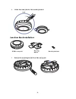
Page 10: ...ket Junction Box Installation 1 Remove the mounting bracket from the access point 840 9502 0006 Lock T bar TM TM Mounting hardware Mounting bracket Mobility point TM AP3950 access point Mounting brack...

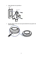
Page 11: ...h the bracket to the junction box 3 Plug the Category 5 cable into the access point and attach the access point to the mounting bracket 840 9502 0017 Junction box Port connector opening 840 9502 0062...

Page 12: ...y 5 cable 2 Remove the mounting bracket from the access point 3 Attach the bracket to the wall or ceiling Mounting hardware Mounting template Mounting bracket Mobility point TM AP3950 access point Mou...

Page 13: ...13 4 Plug the Category 5 cable into the access point and attach the access point to the mounting bracket 840 9502 0016 Universal mounting bracket Cable TM 840 9502 0062 Lock TM TM...

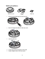
Page 14: ...ach it to the access point 3 Attach the rubber feet 4 Turn the access point over and place it on the table 5 Plug the Category 5 cable into the access point Rubber feet Mounting bracket Mobility point...

Page 15: ...port as an AP3950 managed access point and then insert the cable into the controller and verify the link To connect the access point indirectly to a 3Com Wireless LAN Controller through the network c...

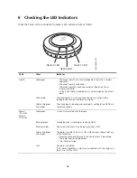
Page 16: ...ng green and amber The access point is booting and receiving its configuration file from a wireless controller Radio 1 2 4 GHz Radio 2 5 0 GHz Solid green A client is associated with the radio Blinkin...

Page 17: ...tic fields 0 Hz to 300 GHz US RADIO FREQUENCY REQUIREMENTS This device must not be co located or operated in conjunction with any other antenna or transmitter This device is for indoor use only when u...

Page 18: ...f est autoris e seulement aux conditions suivantes 1 il ne doit pas produire de brouillage et 2 l utilisateur du dispositif doit tre pr t accepter tout brouillage radio lectrique re u m me si ce broui...

Page 19: ...ve shod se z kladn mi pozadavky a dal mi p slu n mi ustanoven mi sm rnice 1999 5 ES Dansk Danish Undertegnede 3Com Corporation erkl rer herved at f lgende udstyr RLAN device overholder de v sentlige...

Page 20: ...k vetelm nyeknek s az 1999 5 EC ir nyelv egy b el r sainak Malti Maltese Hawnhekk 3Com Corporation jiddikjara li dan RLAN device jikkonforma mal htigijiet essenzjali u ma provvedimenti ohrajn relevant...

Page 21: ...the area The presence of nearby radar operation may result in temporary interruption in communications of this device The Access Point s radar detection feature will automatically restart operation o...

Page 22: ...s reserved 3Com and the 3Com logo are registered trademarks of 3Com Corporation All other company and product names may be trademarks of the respective companies with which they are associated Part Nu...

Reviews: