background image

SERVICE  MANUAL

DIGITAL SOUND PROJECTOR

YSP-1000

CONTENTS

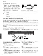
TO SERVICE PERSONNEL .......................................... 2
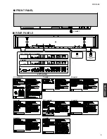
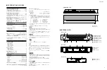
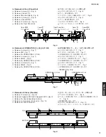
FRONT PANEL 
.............................................................. 3
REAR PANELS 
.............................................................. 3
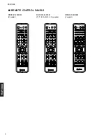
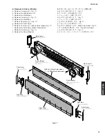
REMOTE CONTROL PANELS 
...................................... 4
SPECIFICATIONS / 

参考仕様

........................................ 5

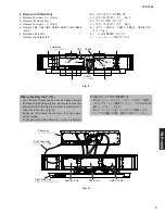
INTERNAL VIEW ........................................................... 5
SET MENU TABLE 
........................................................ 6
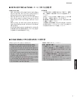
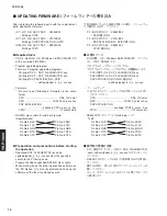
SERVICE PRECAUTIONS 

/ サービス時の注意事項 .....

7

DISASSEMBLY PROCEDURES

 / 分解手順

........... 7~13

UPDATING FIRMWARE

 /

ファームウェアの書き込み

..................................... 14~24

SELF DIAGNOSIS FUNCTION (DIAG)

 /

自己診断機能(ダイアグ)

..................................... 25~42

DISPLAY DATA ........................................................... 43
IC DATA 
................................................................. 44~45
BLOCK DIAGRAM 
................................................. 46~47
PRINTED CIRCUIT BOARD 
.................................. 48~58
PIN CONNECTION DIAGRAM 
.................................... 59
SCHEMATIC DIAGRAM 
........................................ 61~68
PARTS LIST 
........................................................... 69~90
REMOTE CONTROL 
.................................................... 91
YSP-1000 Packing Instruction / 

梱包手順説明書

........ 92

1 0 0 9 6 7

IMPORTANT NOTICE

This manual has been provided for the use of authorized YAMAHA Retailers and their service personnel.
It has been assumed that basic service procedures inherent to the industry, and more specifically YAMAHA Products, are already
known and understood by the users, and have therefore not been restated.

WARNING:

Failure to follow appropriate service and safety procedures when servicing this product may result in personal
injury, destruction of expensive components, and failure of the product to perform as specified.  For these reasons,
we advise all YAMAHA product owners that any service required should be performed by an authorized
YAMAHA Retailer or the appointed service representative.

IMPORTANT:

The presentation or sale of this manual to any individual or firm does not constitute authorization, certification or
recognition of any applicable technical capabilities, or establish a principle-agent relationship of any form.

The data provided is believed to be accurate and applicable to the unit(s) indicated on the cover.  The research, engineering, and
service departments of YAMAHA are continually striving to improve YAMAHA products.  Modifications are, therefore, inevitable
and specifications are subject to change without notice or obligation to retrofit.  Should any discrepancy appear to exist, please
contact the distributor's Service Division.

WARNING:

Static discharges can destroy expensive components.  Discharge any static electricity your body may have
accumulated by grounding yourself to the ground buss in the unit (heavy gauge black wires connect to this buss).

IMPORTANT:

Turn the unit OFF during disassembly and part replacement.  Recheck all work before you apply power to the unit.

P.O.Box 1, Hamamatsu, Japan

 2005                                         All rights reserved.

This manual is copyrighted by YAMAHA and may not be copied or

redistributed either in print or electronically without permission.

YSP-1000

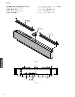
When transporting this unit, be sure to use the unit’s packing materials and box so as to protect
it against any damage, in particular, dents in the front grille during transportation.

本機を輸送する場合、輸送時の破損(特に、フロントグリルのへこみ)等を防ぐために必ず専用の梱
包箱を使用してください。

 '05.10

Summary of Contents for YSP 1000 - Digital Sound Projector Five CH...

Page 1: ...epresentative IMPORTANT The presentation or sale of this manual to any individual or firm does not constitute authorization certification or recognition of any applicable technical capabilities or est...

Page 2: ...rom supply circuits Meter impedance should be equivalent to 1500 ohms shunted by 0 15 F Leakage current must not exceed 0 5mA Be sure to test for leakage with the AC plug in both polarities About Lead...

Page 3: ...YSP 1000 3 YSP 1000 FRONT PANEL REAR PANELS J model IR OUT OPTIMIZER MIC YAPO U C T K A B G L V models J model BOTTOM VIEW U C models T model K model A model B G models V model J model L model...

Page 4: ...ND OFF CODE SET SPORTS 3 4 5 6 7 8 9 0 10 5BEAM ST 3BEAM 3BEAM TARGET MUSIC MOVIE VOL MODE INPUTMODE MACRO INPUT2 INPUT1 AUX YSP CINEMA DSP CH WF72990 TV POWER AV POWER STANDBY ON TV STB VCR DVD TV 2...

Page 5: ...ection Output Level Composite Video 1 Vp p 75 ohms Component Video Y 1 Vp p 75 ohms Pb Pr 0 5 Vp p 75 ohms Frequency Characteristics Composite Video 5 Hz 10 MHz Component Video 5 Hz 60 MHz Speaker Sec...

Page 6: ...15 0 3 0 m 0 1 step 1 0 50 0 7 0 ft 0 5 step MUTE 20dB 0 160mS 1 step SHELF WALL NORMAL HI ECHO MIN STD MAX POSITION INSTALLED HEIGHT RM WDTH C LEFT WALL RM LGTH C RIGHT WALL USER POS L WALL 4 FLAT A...

Page 7: ...parts are reinstalled at specified positions SERVICE PRECAUTIONS INPUT 1 P C B C523 OFF 5 k 10 W C523 P 52 PRINTED CIRCUIT BOARD INPUT 1 P C B P 67 SCHEMATIC DIAGRAM INPUT 2 2 Safety measures Some int...

Page 8: ...3 3 3 3 3 Rear Panel 1 Removal of Top Panels and Plate Top a Remove 8 screws 1 Fig 1 b Remove 2 Top Panels c Remove 2 screws 2 Fig 1 d Remove the Plate Top 1 1 1 1 2 Top Panel Top Panel Plate Top Fig...

Page 9: ...A Fig 3 When checking the P C B The Shield Unit removed from the unit does not work because its grounding is loose Be sure to connect the ground of the Shield Unit to the chassis or GND with a lead wi...

Page 10: ...a 0 4 Fig 5 b CB6 9 Fig 5 c DSP P C B d A 8 Fig 5 e CB507 CB509 512 CB707 CB709 712 Fig 5 f AMP L R P C B 4 Removal of DSP P C B AMP L R P C B a Remove 4 screws 0 Fig 5 b Remove CB6 CB7 CB8 and CB9 Fi...

Page 11: ...e Remove the Driver Tweeter 7 a H 12 Fig 8 b DSP 2 DSP C 2 Fig 9 c d I 2 Fig 10 e 6 OPERATION 1 3 4 P C B a E 6 Fig 7 b CB1 Fig 7 c OPERATION 1 P C B d F 4 Fig 7 e CB301 Fig 7 f OPERATION 3 P C B g G...

Page 12: ...B1 A2 B2 C1 A3 B3 C2 A4 B4 C3 A5 B5 C4 A6 B6 C5 A7 B7 C6 A8 B8 C7 A9 B9 C8 A10 B10 C9 A11 B11 C10 A12 B12 C11 A13 B13 A14 B14 A15 REAR VIEW Rch side Rch Lch side Lch CB510 CB512 CB511 CB709 CB710 CB5...

Page 13: ...M Black Color model Fig 11 i Remove the Grille Ass y Black Color model j Remove 8 screws N Fig 11 k Remove the Driver Woofer 8 a J 4 Fig 11 b L R c d K 4 Fig 11 e f L 18 Fig 11 g h M 16 Black Color mo...

Page 14: ...0 DSP P C B DSP IC17 X7073B00 DSP APPLICATION SPID P C B DSP IC26 X6894A00 CPU DOS V OS Windows 98 2000 Me XP RS232C PC 2 CPU DSP FLASHER YSP exe DSP DSP FLASHER YSP exe DSP APPLICATION SPID spDownloa...

Page 15: ...2C ports with the RS232C cable cross cable Fig 1 Fig 2 BOTTOM VIEW Reset Switch Fig 1 BOTTOM VIEW RS 232C Port RS 232C RS 232C Cable RS 232C Reset Switch 3 While pressing the reset switch of YSP 1000...

Page 16: ...2C Press this button to open the window Select the firmware PC OS Windows 98 2000 Me COM1 4 Windows XP COM1 2 PC The port selection varies depending on OS of the PC Windows 98 2000 Me COM1 4 Windows X...

Page 17: ...re turning on the power to YSP 1000 and PC connect between RS232C ports with the RS232C cable cross cable Fig 1 DSP 1 PC DSP FLASHER YSP exe 2 YSP 1000 PC RS232C RS232C Fig 1 7 OK 7 When the program t...

Page 18: ...RS 232C PC OS Windows 98 2000 Me COM1 4 Windows XP COM1 2 PC The port selection varies depending on OS of the PC Windows 98 2000 Me COM1 4 Windows XP COM1 2 As no port other than the above can be use...

Page 19: ...P 1000 press the STANDBY ON key of the remote control to activate the DIAG function 1 Using the UP or DOWN key of the remote control select the DIAG menu in the figure below 7 YSP 1000 AC YSP 1000 VOL...

Page 20: ...M After downloading successfully the value of SUM from SET is appeared The procedure is completed when the value is obtained for SUM from FILE and SUM from SET Confirm the value of SUM SUM 10 YSP 1000...

Page 21: ...SP 1000 press the STANDBY ON key of the remote control to activate the DIAG function 1 Using the UP or DOWN key of the remote control select the DIAG menu in the figure below DSP APPLICATION SPID 1 PC...

Page 22: ...his button to open the window Select the firmware 1 Press the button beside the Source firmware Box And select the firmware DSP APPLICATION ysp2app_YSP2 0_xxxxx_ hex SPID Y10xxxxxx bin 1 DSP APPLICATI...

Page 23: ...ftware Target Confirm Software Target Software Target Software Target Software Target spDownloader When Source filename is selected Software Target box is selected automatically If Software Target is...

Page 24: ...mote control make a change as shown below LEFT RIGHT 2 Using the LEFT or RIGHT key of the remote control select the DIAG sub menu in the figure below Change 1Ltd to YAMAHA 1Ltd YAMAHA 7 YSP 1000 STAND...

Page 25: ...NTER 4 FRONT R 5 SURROUND R 6 SURROUND L 7 LFE 1 PRO LOGIC I 2 PRO LOGIC II 3 NEO 6 1 MIC CHECK 1 VFD CHECK Initial display 2 VFD DISP OFF All segments OFF 3 VFD DISP ALL All segments ON 100 100 4 VFD...

Page 26: ...Y 22 29 Y 31 30 Y 32 31 MTT 1 MODEL SETTING 2 DESTINATION 3 VIDEO FORMAT 1 VERSION DSP ALL 2 SUM ALL BOOT 1 MAIN 2 SUB 3 SUB 2 4 SUB 3 5 PROTECT 6 REMOTE CONTROL CODE 1 Tx Test Ch 2 Tx Test 3 T1 CHECK...

Page 27: ...e keep pressing those two keys for 3 seconds or longer In this mode the SLEEP segment of the FL display of the main unit flashes to indicate that the mode is DIAG mode with the protection functions di...

Page 28: ...abet and the DIAG menu sub menu THR ALL of DIAG menu No 1 DSP THROUGH a few seconds later Opening message DIAG menu display After a few seconds Version 1 alphabet 1 When there is no history of protect...

Page 29: ...the unit an abnormality which has occurred previously can be defined as long as the backup data has been stored The history of the protection function is cleared when DIAG is cancelled by selecting PR...

Page 30: ...t through SURROUND R only but not in digital full bit DSP THR FRONT R FRONT R output SWFR is output through FRONT R only but not in digital full bit DSP THR CENTER CENTER output SWFR is output through...

Page 31: ...eam TXn beam DD dts AAC multi DIR TI DSP 1 Ti DSP 2 YSS 930 1 DAC DAC OPT1 OPT2 COAX Analog1 Analog2 MIC ADC YSS 930 2 YSS 930 3 L R L R L L L R L R L LFC L BASS SWFR WFL WFR LFC TXn beam TXn beam TXn...

Page 32: ...ull bit RAM THR SURROUND L SURROUND L SWFR SURROUND L RAM THR LFE LFE output RAM THR LFE LFE RAM THR FRONT L FRONT L output SWFR is output through FRONT L only but not in digital full bit RAM THR FRON...

Page 33: ...beam Analog Ti DSP 2 L R SL SR C LFE L R SL SR C LFC DIR TI DSP 1 YSS 930 1 DAC DAC OPT1 OPT2 COAX Analog1 Analog2 MIC ADC YSS 930 2 YSS 930 3 LFE BASS SWFR WFL WFR LFC TXn beam TXn beam TXn beam DD d...

Page 34: ...PRO LOGIC NEO6 PRO LOGIC I II Neo 6 can be selected from the SUB menu items PRO LOGIC I PRO LOGIC EMULATION 3 PRO LOGIC NEO6 PRO LOGIC I II Neo 6 PRO LOGIC I PRO LOGIC EMULATION DIR TI DSP 1 Ti DSP 2...

Page 35: ...ECK This program is used to check the FL display section The display condition varies as shown below according to the sub menu operation The signals are processed using EFFECT OFF The L R signal is ou...

Page 36: ...ST DSP LFE 35 250Hz 800Hz HARD FLOW This sub menu is used to check operation of the flow port of the hardware OK appears when the check result is satisfactory and NG when it is not Hard Flow OK NG 7 R...

Page 37: ...ection detection PS Power supply voltage protection value Normal value PS 50 to 88 If PS is out of the normal value range the protection function works to turn off the power Reference voltage 3 3V 100...

Page 38: ...f the input signal IEC60958 BS1 7 Indicates information of the bit stream included in the dts and AAC signal MTT Mute Trigger CS1 6 IEC60958 BS1 7 dts AAC MTT Mute Trigger 1st byte 5th byte 4th byte 3...

Page 39: ...and expressing the result as a 4 figure hexa decimal data Numeric values in the figure example are for reference 12 2 OFF 16 4 16 Version Checksum 11 MODEL The information on the model destination and...

Page 40: ...in the figure example are for reference 13 DATE 6 Remo Code INPUT PROTECT HISTORY DELETE Reserve Cancel can be selected by using the ENTER and RETURN keys of the remote control ENTER RETURN REMOTE CON...

Page 41: ...detected SRAM I F Error of IF with FLASH ROM detected FLASH ROM I F Error other than above detected Function not applicable Display Not Checked Wait No Error Err DSP Err SRAM Err FLASH Err Unknown res...

Page 42: ...viation for the Sound Projector Module Initialization Data Format SPD SPID SPID Sound Projector Module Initialization Data Format VR1 Not applied to this model VR1 T1 Write Select OFF ON of firmware w...

Page 43: ...on Note 1 F1 F2 Filament 2 NP No pin 3 NX No extened Pin 4 1G 15G Grid 1G 14G 15G 1 1 2 1 3 1 4 1 5 1 1 2 2 2 3 2 4 2 5 2 1 3 2 3 3 3 4 3 5 3 1 4 2 4 3 4 4 4 5 4 1 5 2 5 3 5 4 5 5 5 1 6 2 6 3 6 4 6 5...

Page 44: ...0 41 42 43 44 45 46 47 48 49 50 51 52 53 54 55 56 57 58 59 60 61 62 63 64 65 66 67 68 69 70 71 72 73 74 75 76 77 78 79 80 81 82 83 84 85 86 87 88 89 90 91 92 93 94 95 96 97 98 99 100 P0_0 AN0_0 D0 P0_...

Page 45: ...to back end DSP I2C DATA signal to back end DSP RS 232C data output for com flash writing RS 232C data input for com flash writing RS 232C clock output for com flash writing RS 232C BUSY output for c...

Page 46: ...2 TIBSDO4 IC20 3 L CH DRIVER TWEETER x20 37 YCBCK IC23 91 38 YCWCK 90 27 YCSD00 99 28 YCSD01 98 29 YCSD02 IC715 97 30 YCSD03 10 11 IC2 IC9 IC26 92 31 YCSD04 1 1 8 32 YCSD05 14 15 49 4 IC10 6 IC1 94 95...

Page 47: ...C510 TH501 C523 C533 C534 C535 C556 C557 C502 D503 Q501 IC502 IC501 T501 IC503 D507 5V 5VA MGND 12V 12B 12A 12V AGND AGND AGND 24V POW_RY S3 3 S3 3BK GND PW_DOWN RESET RESET CIRCUIT Q502 Q504 1 14 3 5...

Page 48: ...V_MUTE DEST CNVSS AGND AGND 12A 12V 12V 5V GND GND 24V S3 3 S3 3BK RES PW_DOWN PW_RY TEMP INPUT 1 CB508 INPUT 2 CB3 OPERATION 4 CB302 OPERATION 1 CB1 to MAIN U COM WRITER AGND YBSDO4 YCSDO3 YCSDO4 YBS...

Page 49: ...50 76 26 100 75 51 1 25 50 76 26 100 75 51 1 25 50 76 26 100 1 20 10 11 1 20 10 11 1 14 7 8 1 4 8 5 Semiconductor Location D1 B4 D2 B3 D3 E5 D7 F3 D8 F3 D9 F3 D10 F3 D11 H3 D12 H3 IC6 F5 IC10 F3 IC13...

Page 50: ...ND3 INPUT 1 CB504 DSP CB8 P6L N6L P6R N6R P5L N5L P5R N5R P8L N8L P8R N8R P7L N7L P7R N7R P9L N9L P9R N9R N0R P0R N0L P0L N1R P1R N1L P1L N2R P2R N2L P2L N3R P3R N3L P3L N4R P4R N4L P4L DRIVER WOOFER...

Page 51: ...K1 DGND D3MUTEN PROTN AGND AGND DSP CB9 P6L N6L P6R N6R P5L N5L P5R N5R P8L N8L DRIVER x 5 TWEETER DRIVER x 5 TWEETER P8R N8R P7L N7L P7R N7R P9L N9L P9R N9R DRIVER x 5 TWEETER N0R P0R N0L P0L N1R P1R...

Page 52: ...8 C4 D531 F6 D542 C5 IC501 D3 IC502 E3 IC503 D2 IC504 F6 IC506 B3 IC507 E5 IC509 B4 IC510 B4 IC511 C3 IC512 F6 Q501 F3 Ref No Location Ref No Location Ref No Location Ref No Location C523 OFF 5 k 10 W...

Page 53: ...NTED CIRCUIT BOARD Foil side 1 8 4 5 Semiconductor Location D502 E2 D504 D3 D507 F3 D508 E3 D509 D3 D512 C2 Ref No Location D513 C3 D514 C3 D519 B3 D520 B3 D521 B3 D526 B4 D527 C4 D529 B4 D530 C3 D532...

Page 54: ...2B I_SEL0 I_SEL1 AOL AGND AOR AGND SW_OUT V_SEL0 V_SEL1 V_SEL2 V_MUTE DEST CN_VSS AGND AGND A12V 5VA S3 3 12B GND GND DSP W2 DSP W3 INPUT 1 CB4 RS 232C REMOTE IN AUDIO IN TV STB SUBWOOFER DVD COAXIAL...

Page 55: ...2 13 24 37 36 25 48 5 8 1 4 1 3 5 4 X NOT USED O USED APPLICABLE Semiconductor Location D1 E4 D2 E4 D3 E4 D4 E4 D5 G4 D6 I4 D7 H5 D8 J5 IC1 D3 IC2 G3 IC3 B4 IC4 E4 IC5 E5 IC6 H4 IC7 F4 IC9 F4 IC10 H4...

Page 56: ...Foil side INPUT 3 P C B Side A 12B AGND OPERATION 4 CB301 IR OUT 1 8 5 4 INPUT 3 P C B Side B Lead Free Solder Used Semiconductor Location D401 G3 D402 G4 D403 F3 D404 G4 D405 F4 D406 B4 D407 B4 D408...

Page 57: ..._CLK FL_TXD FL_ON REMOTE S3 3 24V FL40KHz STBY_SW KEY0 KEY1 FL DISPLAY REMOTE CONTROL SENSOR KEY0 KEY1 S3 3 STBY_SW GND GND OPERATION 1 P C B Side B Lead Free Solder Used 1 16 17 32 33 48 49 64 Semico...

Page 58: ...MICA MIC_DET A12V AGND FG 1 8 4 5 OPERATION 3 W1 DSP CB7 INPUT 3 W401 MICA MIC_DET A12V AGND GND GND 12B 12B MIC_DET A12V MICA AGND FG OPERATION 2 P C B Side B Lead Free Solder Used OPERATION 3 P C B...

Page 59: ...5 1 10 20 16 8 1 WM8738 14 7 1 W9864G6EH 7 54 1 28 27 W9816G6CH 7 50 1 26 25 MBM29LV160BE 70TN MBM29LV400BC 70PFT 1 24 48 FA3641N H1 TE1 NJM431 8 4 1 8 4 1 3 CATHODE 2 ANODE 1 REF BA7611AF 1 4 8 M6278...

Page 60: ...YSP 1000 60 MEMO MEMO...

Page 61: ...RIN LIN DVDD DGND SDATO LRCLK BCLK MCLK VREF FMT NOHP ADC ADC DIGITAL FILTERS AUDIO INTERFACE CONTROL INTERFACE IC10 WM8738 24bit Stereo ADC V SS V CC WE CE A0 to A17 OE Erase Voltage Generator DQ 0...

Page 62: ...ANK 3 DATA CONTROL CIRCUIT DQ BUFFER COLUMN DECODER SENSE AMPLIFIER CELL ARRAY BANK 1 ROWDECODER A0 A9 BS0 BS1 CS RAS CAS WE A11 ROWDECODER COLUMN DECODER SENSE AMPLIFIER COLUMN DECODER SENSE AMPLIFIE...

Page 63: ...19 20 YSS930 SZ DSP IC21 SN74AHC1G08DCKR 2 Input And Gate IC25 NJM2068MD TE2 Dual OP Amp OUT1 IN1 VCC VCC OUT2 1 2 3 4 5 IN1 IN2 IN2 6 7 8 B 2 POINT B 2 Pin 13 of IC26 0 3 3 3 2 2 5 3 3 3 2 1 7 1 7 0...

Page 64: ...0 1 0 2 5 2 5 3 2 2 6 2 3 5 2 0 1 0 1 5 2 5 1 0 2 6 5 2 0 0 0 0 0 2 5 5 2 0 1 0 1 0 2 5 2 5 3 2 2 6 2 3 5 2 0 1 0 1 5 2 5 1 0 2 6 5 2 0 0 0 0 0 2 5 5 2 0 1 0 1 0 2 5 2 5 3 2 2 6 2 3 5 2 0 1 0 1 5 2 5...

Page 65: ...3 2 0 0 0 0 5 2 0 1 0 1 0 1 0 1 0 0 0 2 5 2 5 5 2 5 2 5 2 5 1 2 5 2 6 2 6 2 3 3 2 0 0 0 0 5 2 0 1 0 1 0 1 0 1 0 0 0 2 5 2 5 5 2 5 2 5 2 5 1 2 5 2 6 2 6 2 3 3 2 0 0 0 0 5 2 0 1 0 1 0 1 0 1 0 0 0 2 5 2...

Page 66: ...TC74HCT08AF Quad 2 Input And Gate Vcc 14 4B 13 4A 12 4Y 11 3B 10 3A 9 3Y 8 1A 1 1B 2 1Y 3 2A 4 2B 5 2Y 6 GND 7 FLDI VSYNCI HSYNCI VCC VSS EXS XS FSC4O VSYNCO HSYNCO CSYNCO VBLKO 1 2 3 4 5 6 7 8 9 10 1...

Page 67: ...Flip Flop 4 RESET1 1 Q1 6 SET1 5 DATA1 CL 3 CLOCK1 CL CL CL CL CL 2 Q1 10 RESET2 13 Q2 8 SET2 9 DATA2 7 VSS 14 VDD 11 CLOCK2 12 Q2 CL CL CL CL CL CL 7 2 1 3 4 5 6 8 Error Amp Starter Voltage Referenc...

Page 68: ...3 3 24 1 24 7 3 3 0 4 9 0 3 0 0 3 3 0 4 6 17 5 22 5 22 5 22 5 22 5 22 5 22 5 22 5 22 5 22 5 22 5 22 5 22 5 22 5 22 5 22 5 17 8 19 3 19 3 19 3 17 8 17 7 24 1 24 1 22 5 16 2 17 8 22 5 22 5 22 5 17 8 19...

Page 69: ...FLTR LC RF LC FILTER EMI GND MTL GROUND PLATE GND TERM GROUND TERMINAL HOLDER FUS FUSE HOLDER IC PRTCT IC PROTECTOR JUMPER CN JUMPER CONNECTOR JUMPER TST JUMPER TEST POINT L DTCT LIGHT DETECTING MODU...

Page 70: ...uF 16V 01 C29 US063100 C CE CHP 1000pF 50V B 01 C30 39 US135100 C CE CHP 0 1uF 16V 01 C40 49 US135100 C CE CHP 0 1uF 16V 01 C50 UF017470 C EL CHP 47uF 6 3V 01 C51 52 US135100 C CE CHP 0 1uF 16V 01 C53...

Page 71: ...V 01 C190 UF017470 C EL CHP 47uF 6 3V 01 C191 192 US035100 C CE CHP 0 1uF 16V B 01 C193 195 US063100 C CE CHP 1000pF 50V B 01 C196 198 US035100 C CE CHP 0 1uF 16V B 01 C199 US063100 C CE CHP 1000pF 50...

Page 72: ...305 306 US135100 C CE CHP 0 1uF 16V 01 C307 UF038100 C EL CHP 100uF 16V 01 C308 UF018100 C EL CHP 100uF 6 3V 01 C309 377 US035100 C CE CHP 0 1uF 16V B 01 C378 380 US065100 C CE CHP 0 1uF 50V B C381 US...

Page 73: ...CB707 LB918030 CN BS PIN 3P 01 CB709 VL845500 CN BS PIN 11P TE 01 CB710 VL845400 CN BS PIN 10P 01 CB711 VL845500 CN BS PIN 11P TE 01 CB712 VL845400 CN BS PIN 10P 01 C501 US145100 C CE CHP 0 1uF 25V 0...

Page 74: ...1 US135100 C CE CHP 0 1uF 16V 01 C572 US126100 C CE CHP 1uF 10V 01 C575 US126100 C CE CHP 1uF 10V 01 C576 UR818220 C EL 220uF 6 3V 01 C577 US126100 C CE CHP 1uF 10V 01 C578 UR818220 C EL 220uF 6 3V 01...

Page 75: ...CHP 1uF 10V 01 C727 UR818220 C EL 220uF 6 3V 01 C729 UR837100 C EL 10uF 16V 01 C730 UR866100 C EL 1uF 50V 01 C731 US135100 C CE CHP 0 1uF 16V 01 C732 UR866100 C EL 1uF 50V 01 C733 US135100 C CE CHP 0...

Page 76: ...6V 01 C819 US135100 C CE CHP 0 1uF 16V 01 C824 UR839100 C EL 1000uF 16V 01 C825 UR829100 C EL 1000uF 10V 01 C826 827 US145100 C CE CHP 0 1uF 25V 01 C828 829 US126100 C CE CHP 1uF 10V 01 D501 510 VT332...

Page 77: ...4 LB932060 CN BS PIN 6P 01 CB507 LB932060 CN BS PIN 6P 01 CB508 VF283300 CN BS PIN 15P 01 CB509 VG879900 CN BS PIN 2P 01 C1 US064100 C CE CHP 0 01uF 50V B 01 C2 US064100 C CE CHP 0 01uF 50V B 01 C3 US...

Page 78: ...C76 UA655220 C MYLAR 0 22uF 50V J 01 C77 UR837470 C EL 47uF 16V 01 C78 UR818100 C EL 100uF 6 3V 01 C79 US035100 C CE CHP 0 1uF 16V B 01 C80 US064100 C CE CHP 0 01uF 50V B 01 C81 UR818100 C EL 100uF 6...

Page 79: ...C PP 0 022uF 630V TKABGL 01 s C516 WE468500 C CE SAFTY 0 22uF 275V C517 US063100 C CE CHP 1000pF 50V B 01 C518 UA654100 C MYLAR 0 01uF 50V J 01 C519 UR866220 C EL 2 2uF 50V 01 C520 521 VZ243300 C CE C...

Page 80: ...ODE D5SBA60 5 0A 600V TKABGL 04 D512 514 VT332900 DIODE 1SS355 01 D515 VN478200 DIODE D1NL20U 01 D516 WE427100 DIODE ZENR 1Z180 TPA2 180V JUCV D516 WG012200 DIODE ZENR 1Z330 TPA2 330V TKABGL D517 VU07...

Page 81: ...N JACK 4P R BE G Y Y PJ8 WG089100 JACK PIN JACK 4P R BE G Y Y PN501 V8637500 PIN L 50 18 Q1 VV556400 TR 2SC2412K Q R S 01 Q2 VV556400 TR 2SC2412K Q R S 01 Q3 VV556400 TR 2SC2412K Q R S 01 Q4 VV556400...

Page 82: ...3x8 MFZN2B3 01 WG115600 P C B OPERATION CB1 VE352600 CN BS PIN 14P 01 CB3 VB390200 CN BS PIN 6P 01 CB301 VB389800 CN BS PIN 2P 01 CB302 VB390200 CN BS PIN 6P 01 CB303 VB390100 CN BS PIN 5P 01 C1 US06...

Page 83: ...TR 2SC2412K Q R S 01 Q2 VV556400 TR 2SC2412K Q R S 01 Q3 VV556400 TR 2SC2412K Q R S 01 Q4 VV556400 TR 2SC2412K Q R S 01 Q5 VV556400 TR 2SC2412K Q R S 01 Q6 VV556400 TR 2SC2412K Q R S 01 Q7 VV556400 TR...

Page 84: ...01 R CHP 1 2K 1 16W J 0816 01 R CHP 1 5K 1 16W J 0816 01 R CHP 1 8K 1 16W J 0816 01 R CHP 2K 1 16W J 0816 01 R CHP 2 2K 1 16W J 0816 01 R CHP 2 4K 1 16W J 0816 01 R CHP 3K 1 16W J 0816 01 R CHP 3 3K...

Page 85: ...CHP 1M 1 16W J 0816 01 R MTL CHP 470 1 16W D 0816 01 R MTL CHP 12K 1 16W D 0816 01 R CHP 75 1 16W F 0816 LEAD FREE R CHP 120 1 16W F 0816 LEAD FREE 01 R CHP 910 1 16W F 0816 LEAD FREE 01 R CHP 1 0K 1...

Page 86: ...M HJ35 9470 HF85 9470 Value 1 4W Type Part No 1 6W Type Part No 1 0 HJ35 3100 HF85 3100 1 8 HJ35 3180 2 2 HJ35 3220 HF85 3220 3 3 HJ35 3330 HF85 3330 4 7 HJ35 3470 HF85 3470 5 6 HJ35 3560 HF85 3560 1...

Page 87: ...0x20 8 10 20 3 101 WE774300 BIND HEAD B TIGHT SCREW 3x8 MFZN2W3 01 3 103 WE774100 BIND HEAD BONDING B T SCREW 3x8 MFZN2B3 01 3 105 VH365800 PW HEAD B TIGHT SCREW 3x6 8 MFC2 01 3 106 WE877800 BIND HEAD...

Page 88: ...s 302 WE258800 POWER CABLE 2m GL s 302 WE258300 POWER CABLE 2m V 303 V6508900 VIDEO PIN CABLE 1P 1 5m YE 1pc 03 304 V6509000 AUDIO PIN CABLE 2P 1 5m RE WH 1pc 04 305 WE818700 DIGITAL AUDIO PIN CABLE...

Page 89: ...arkets Rank 2 3 WG114800 P C B ASS Y AMP 2 4 WG114900 P C B ASS Y DSP 2 11 WG167600 FLEXIBLE FLAT CABLE 30P 50mm P 1 0 2 15 WF536700 FRONT GRILLE BL 2 15 WD831100 FRONT GRILLE SI 12 2 21 WD831500 COVE...

Page 90: ...UCTKABGLV 2 1 25 WF538600 GRILLE SPEAKER ASS Y BL 2 1 31 WF538400 SUPPORT GRILLE L 2 1 32 WF538500 SUPPORT GRILLE R 2 1 33 WF539000 STOPPER FRAME 2 1 51 WE993900 CUSHION 520x4 t 1 2 1 52 WE203200 PACK...

Page 91: ...5 6_ 6 AAC J model 7_MUSIC 7 8_MOVIE 8 9_VOL MODE 9 0_SPORTS 10 0 10_OFF 11 10 SURROUND 12 MENU RETURN UP DOWN LEFT RIGHT ENTER CH LEVEL CH TEST VOLUME VOLUME CH CH TVVOL TVVOL MUTE TV INPUT TV MUTE C...

Page 92: ...YSP 1000 92 Fold down the lid aps of the shipping box and seal the box with packing tape 5 Packing tape 1 3 2 4 YSP 1000 Packing Instruction 3 1 2 4 5...

Reviews: